Developing device

a technology of developing device and developer, which is applied in the direction of electrographic process apparatus, instruments, optics, etc., can solve the problems of non-uniformity and fog, affecting the generating image defects such as scattering fog or the like, so as to achieve stable effect of discharge of the developer, reduce the flowability of the developer, and feed the developer smoothly

Active Publication Date: 2016-07-28
CANON KK
View PDF0 Cites 6 Cited by
  • Summary
  • Abstract
  • Description
  • Claims
  • Application Information

AI Technical Summary

Benefits of technology

[0007]The present invention has been accomplished in view of the above-described circumstances. A principal object of the present invention is to provide a developing device capable of stably effecting discharge of a developer by smoothly feeding the developer even when a flowability of the developer lowers.

Problems solved by technology

When the toner charge amount lowers, an image defect such as scattering fog or the like is liable to generate.
This agglomerate blocks a feeding path of the developer and impairs the discharge of the developer.
As a result, the amount of the developer discharged through the discharge opening decreases and thus the developer amount in the developing container becomes excessive, so that inconveniences such as generation of density non-uniformity and fog and overflow of the developer from the developing container can occur.
However, in such a case that a continuous operation is performed for a long time in a high temperature / high humidity environment (in this case, the flowability of the developer particularly in the developing container lowers), the amount of the developer discharged through the discharge opening largely decreased in some instances.
At this time, the developer in a large amount is fed at once, and therefore in the neighborhood of the disk portion and the third spiral portion, a new agglomerate is liable to be formed around the third spiral portion, so that the newly formed agglomerate impairs smooth discharge of the developer.

Method used


Image

  • Developing device
  • Developing device
  • Developing device

Examples


Embodiment Construction

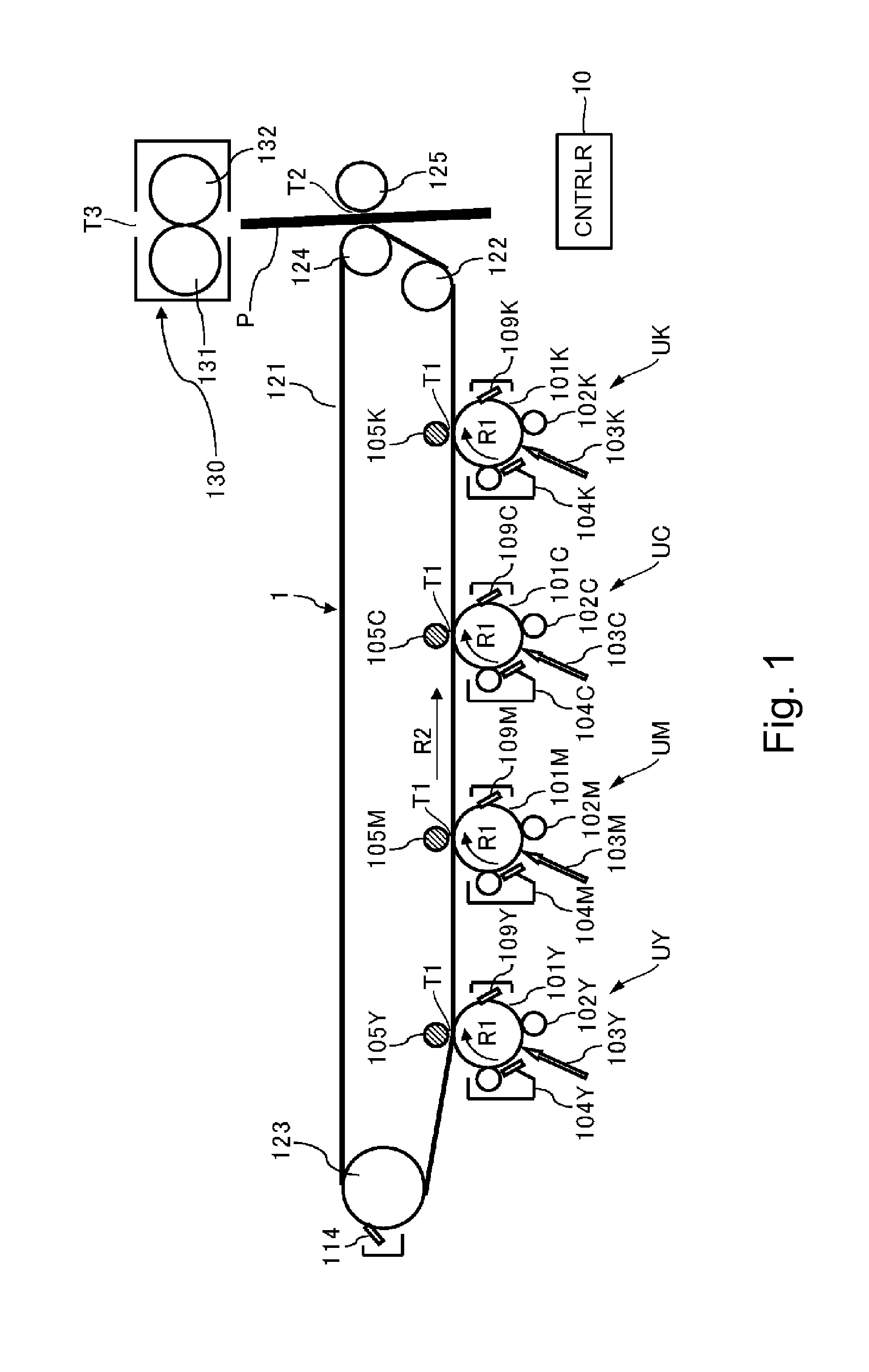
[0017]A developing device according to an embodiment of the present invention will be described. First, a general structure of an image forming apparatus including the developing device according to the present invention will be described with reference to FIG. 1. An image forming apparatus 1 shown in FIG. 1 is an intermediary transfer type full color printer of a tandem type in which image forming portions UY, UM, UC and UK are arranged along an intermediary transfer belt 121.

[0018]At the image forming portion UY, a yellow toner image is formed on a photosensitive drum 101Y and then is transferred onto the intermediary transfer belt 121. At the image forming portion UM, a magenta toner image is formed on a photosensitive drum 101M and then is transferred onto the intermediary transfer belt 121. At the image forming portion UC and UK, cyan and black toner images are formed on photosensitive drums 101C and 101K respectively, and then are transferred onto the intermediary transfer bel...


PUM


Abstract

A developing device includes a developer carrying member, a first chamber, a second chamber, a first feeding member, and a second feeding member. The second feeding member includes first to third spiral portions and a disk portion. The disk portion includes a projected portion. When the disk portion is seen in an axial direction of the second feeding member, on the basis of a line connecting a rotation center of the disk portion and an upstream end portion of the third spiral portion with respect to a feeding direction of the third spiral portion, the projected portion is provided within a range from a position deviated by 90 degrees toward a downstream side with respect to a rotational direction of the disk portion to a position deviated by 30 degrees toward an upstream side with respect to the rotational direction of the disk portion.

Description

FIELD OF THE INVENTION AND RELATED ART[0001]The present invention relates to a developing device used in an image forming apparatus employing an electrophotographic type or an electrostatic recording type, and particularly relates to the developing device for feeding the developer in a developing container to a discharge opening to discharge the developer to an outside of the developing container through the discharge opening.[0002]In the developing device used in the image forming apparatus such as copying machine, a printer, a facsimile machine or a multi-function machine, an one-component developer consisting of a toner alone or a two-component developer consisting of the toner and a carrier (hereinafter, these developers are simply referred to as a developer). These developers are consumed by being subjected to development, and therefore a toner charge amount of the developer remaining in the developing container lowers. When the toner charge amount lowers, an image defect such ...

Claims


Application Information

Patent Timeline
Patent Type & Authority Applications(United States)
IPC IPC(8): G03G15/08
CPCG03G15/0891G03G15/0893
Inventor NOSE, KATSUYASAITO, FUMIYOSHIYAGO, TOSHIHISAMUGITA, NAOKIISHIDA, YUSUKETAKEUCHI, KOSUKE
Owner CANON KK
Why Eureka
Try Eureka