Motor Winding Structure

a technology of motor winding and structure, which is applied in the direction of winding conductor shape/form/construction, etc., can solve the problems of increasing the manufacturing and the arrangement of the jumpers increasing the thickness of the board, so as to reduce the production cost and structural complexity of the motor winding structure, and simplify the manufacturing process

Active Publication Date: 2016-07-28
SUNONWEALTH ELECTRIC MACHINE IND
View PDF4 Cites 26 Cited by
  • Summary
  • Abstract
  • Description
  • Claims
  • Application Information

AI Technical Summary

Benefits of technology

[0033]In each of the motor winding structures above, two circumferentially adjacent coils may be electrically connected to each other via the centers of said coils. Therefore, after the base plate is folded, all of the coils of the winding unit may be electrically connected to each other without having to arrange any conducting hole on the boards. Advantageously, the production cost and structural complexity of the motor winding structure can be lowered and the manufacturing process can be simplified.

Problems solved by technology

However, arrangement of the conducting hole and the conducting element increases the manufacturing cost and structural complexity of the motor 8.
Furthermore, arrangement of the jumpers increases the thickness of the board 821, which is against the purpose of miniaturization as required by the motor 8.
However, arrangement of the conducting hole and the conducting element increases the manufacturing cost and structural complexity of the motor winding structure 9.
However, the insulation treatment makes the production of the motor winding structure 9 inconvenient and may increase the thickness of the motor winding structure 9.

Method used


Image

  • Motor Winding Structure
  • Motor Winding Structure
  • Motor Winding Structure

Examples


first embodiment

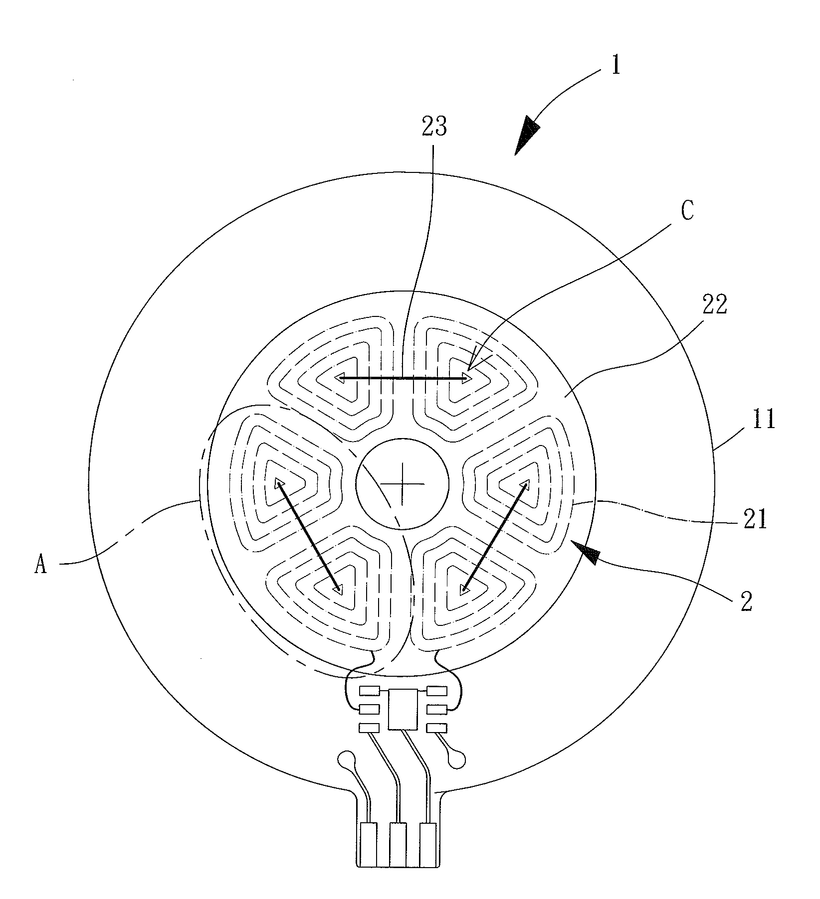
[0048]FIG. 3 shows a motor winding structure according to the invention, which includes a base plate 1. The base plate 1 includes at least one board 11. Each board 11 is provided with a winding unit 2. The winding unit 2 may be arranged on the surface of the board 11.

[0049]The winding unit 2 may be arranged on the surface of the board 11 by electroforming or printing process. When the at least one board 11 includes a plurality of boards 11 (arranging from the 1st to nth boards 11 in sequence), the motor winding structure also includes a plurality of winding units 2 arranged on the plurality of boards 11. Each board 11 is provided with a respective one of the winding units 2. Each winding unit 2 is comprised of a plurality of coils 21. The plurality of coils 21 may be arranged on the board 11 by electroforming or printing process.

[0050]Each coil 21 has an inner end adjacent to a center “C” of the coil 21, as well as an outer end distant to the center “C” of said coil 21. The inner en...

second embodiment

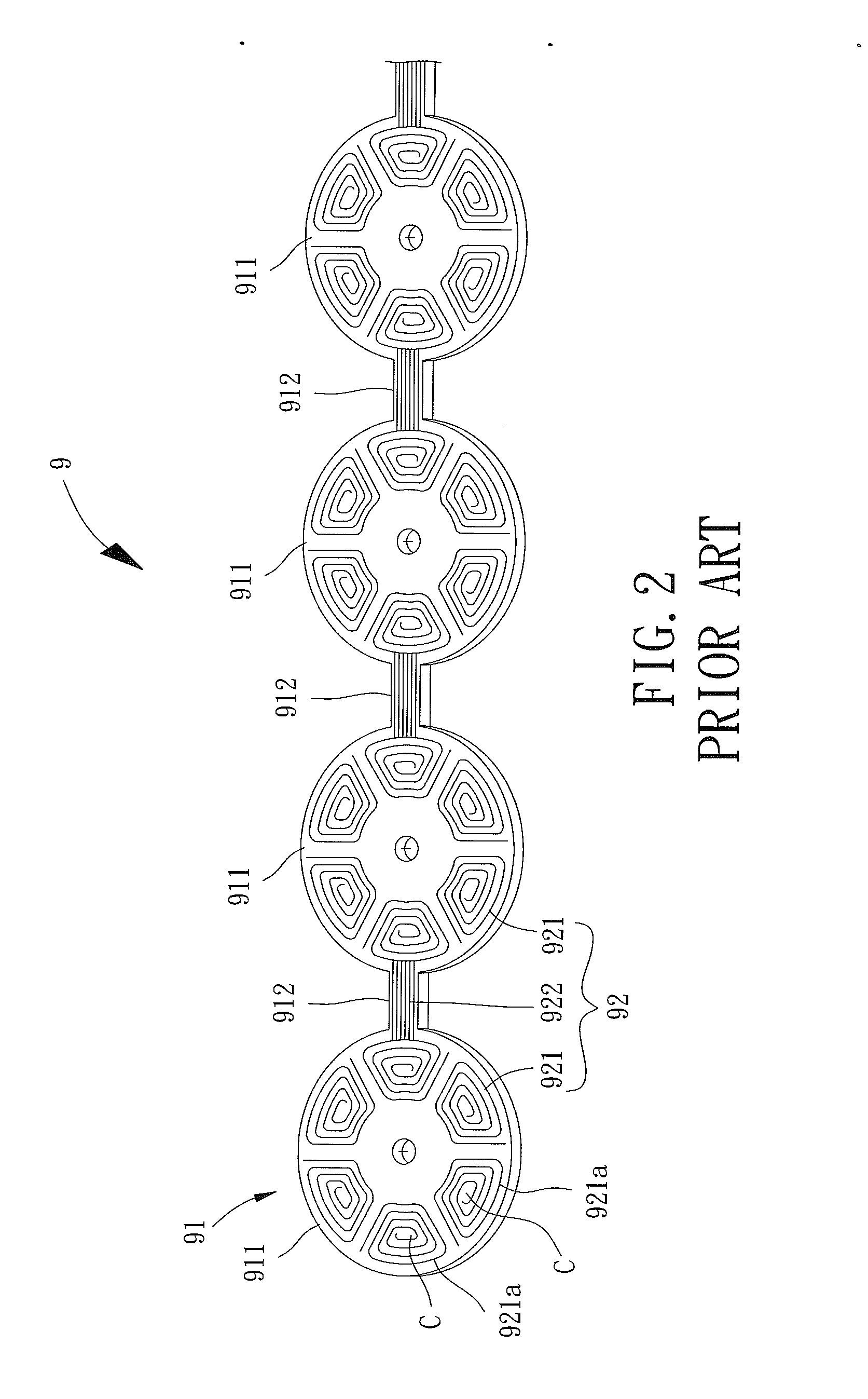
[0056]When the motor winding structure of the second embodiment is used in a motor, the base plate 1 can be folded at the bridges 12 to stack the plurality of boards 11 together, forming a multi-layered winding structure. The plurality of boards 11 may be fixed together by pressing or adhesion. Thus, as shown in FIG. 6, the coils 21 of the winding units 2 on the boards 11 are aligned with each other along an axial direction of the motor winding structure. Accordingly, the number of effective turns of the coils 21 is increased. Since the adjacent two coils 21 can be connected to each other via either inner ends or outer ends thereof, electrical connection between the winding units 2 can be achieved after the base plate 1 is folded without forming any conducting hole on the boards 11. Advantageously, the production cost and structural complexity of the motor winding structure are reduced.

[0057]Referring to FIG. 4 again, the winding unit 2 on each of the boards 11 is comprised of a plu...


PUM


Abstract

A motor winding structure includes a base plate is disclosed. The base plate includes a board having a winding unit. The winding unit includes a plurality of coils formed on the surface of the board by electroforming or layout. Each coil has a center, and includes an inner end adjacent to the center and an outer end distant to the center. Two adjacent coils are connected to each other via the inner ends. The winding unit further includes an insulating layer and a conducting layer. The inner ends of the two coils are connected to an electrical connection pad. The insulating layer is arranged on the board. The two adjacent coils are covered by the insulating layer. The conducting layer extends through the insulating layer and is connected to the electrical connection pads of the two coils. The two coils are connected to each other via the inner ends.

Description

BACKGROUND OF THE INVENTION[0001]1. Field of the Invention[0002]The present invention generally relates to a motor winding structure and, more particularly, to a motor winding structure that allows a plurality of coils thereof to be electrically connected together without having to arrange any conducting hole on the base plate of the motor winding structure.[0003]2. Description of the Related Art[0004]FIG. 1 shows a conventional motor 8 including a base plate 81, a winding assembly 82 and a rotor 83. The winding assembly 82 is coupled with the base plate 81, and the rotor 83 is rotatably coupled with the base plate 81. The winding assembly 82 includes a board 821 and a plurality of coils 822 arranged on the board 821. The plurality of coils 822 is arranged on the board 821 by electroforming or layout. In this arrangement, the plurality of coils 822 is magnetically linked with the rotor 83, driving the rotor 83 to rotate. Such a motor can be seen in Taiwan Patent No. 1384723.[0005]In...

Claims


Application Information

Patent Timeline
Patent Type & Authority Applications(United States)
IPC IPC(8): H02K3/26
CPCH02K3/26
Inventor CHEN, GUAN-MINGLIN, CHANG-YU
Owner SUNONWEALTH ELECTRIC MACHINE IND
Why Eureka
Try Eureka