Direct view optical sight with integrated laser system

a laser system and optical sight technology, applied in the direction of optical elements, distance measurement, instruments, etc., can solve the problems of difficult to maintain alignment at long ranges, difficult to keep tight alignment between an object scene and a laser rangefinder or laser designator, and complicated approach

Active Publication Date: 2016-08-04
RAYTHEON CO
View PDF3 Cites 25 Cited by
  • Summary
  • Abstract
  • Description
  • Claims
  • Application Information

AI Technical Summary

Benefits of technology

[0006]According to one embodiment, a direct view optical sight has an integrated laser rangefinder, and comprises an eyepiece, an objective providing an optical aperture and configured to direct electromagnetic radiation from a viewed scene to the eyepiece, an erector tube assembly coupled between the eyepiece and the objective, the laser rangefinder configured to transmit and receive laser radiation, and a beam combiner assembly mounted to the erector tube assembly and positioned between the erector tube assembly and the objective, the beam combiner assembly configured to combine the laser radiation and the electromagnetic radiation to allow the laser rangefinder to transmit and receive the laser radiation via the optical aperture of the objective, and to maintain optical alignment of the laser rangefinder and the viewed scene during movement of the erector tube assembly.

Problems solved by technology

It is difficult to keep tight alignment between an object scene and laser rangefinders or laser designators while making adjustments such as moving a reticle during bore-sighting or weapon zeroing.
However, if multiple apertures are used, the tolerances between the different systems must be added and make it difficult to maintain alignment at long ranges.
Thus, this approach is complicated, and adds expensive mechanical structure that adds significantly to the cost and weight of the sight.

Method used


Image

  • Direct view optical sight with integrated laser system
  • Direct view optical sight with integrated laser system
  • Direct view optical sight with integrated laser system

Examples


Embodiment Construction

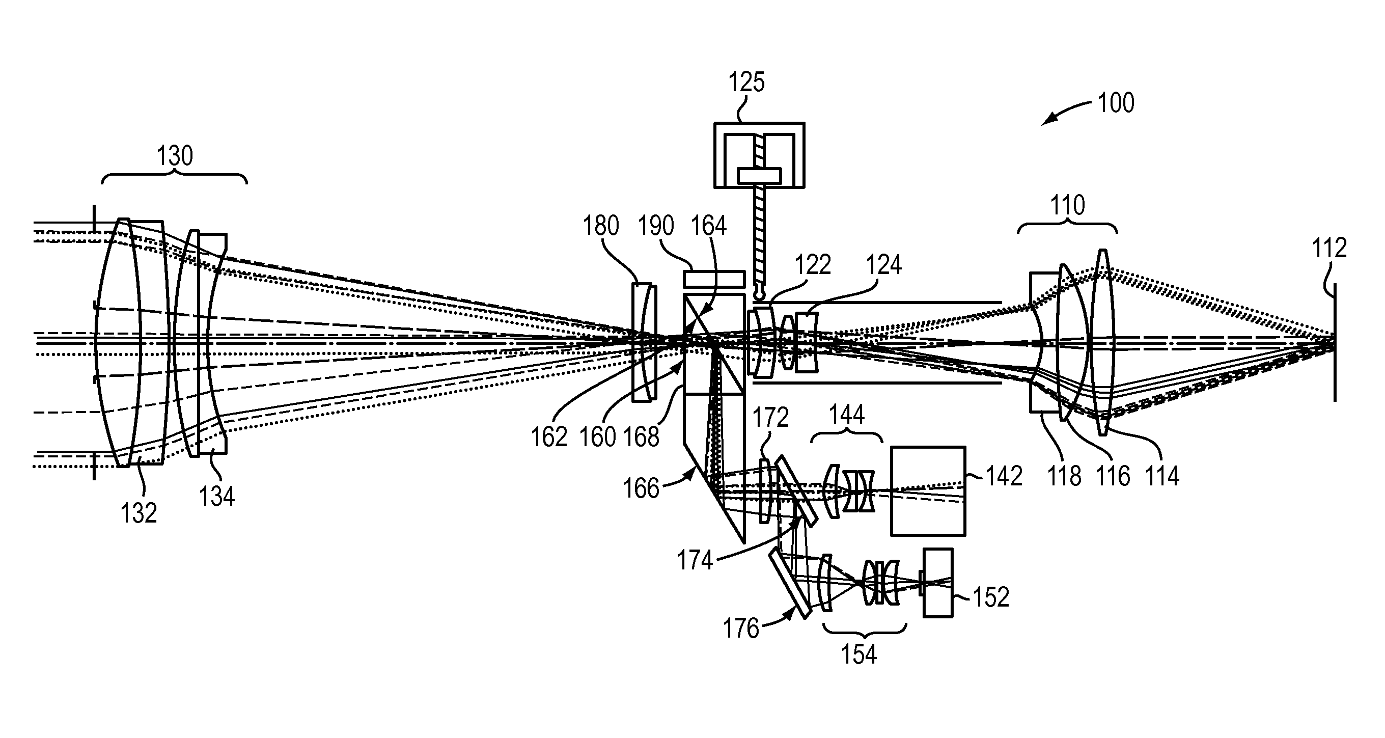
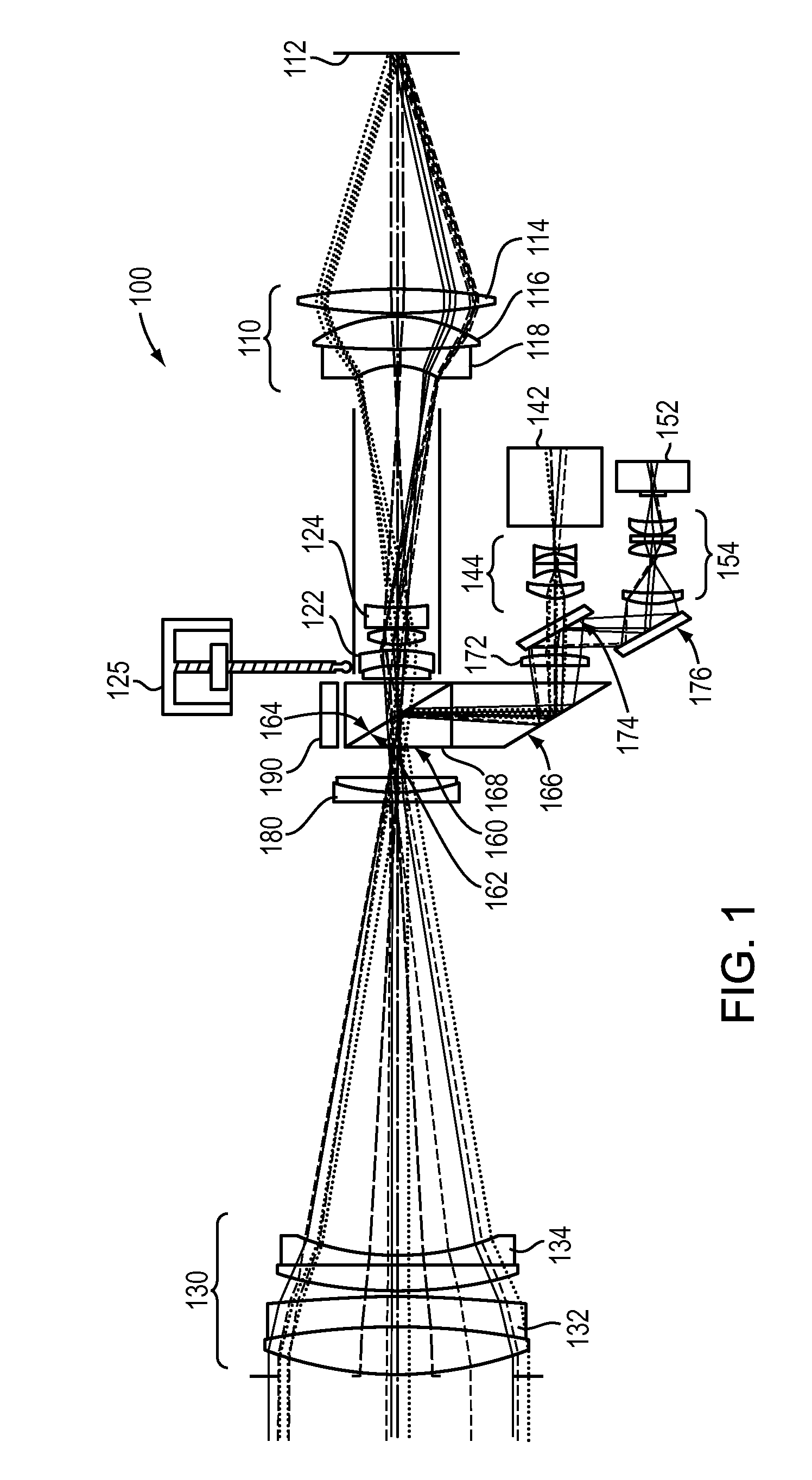
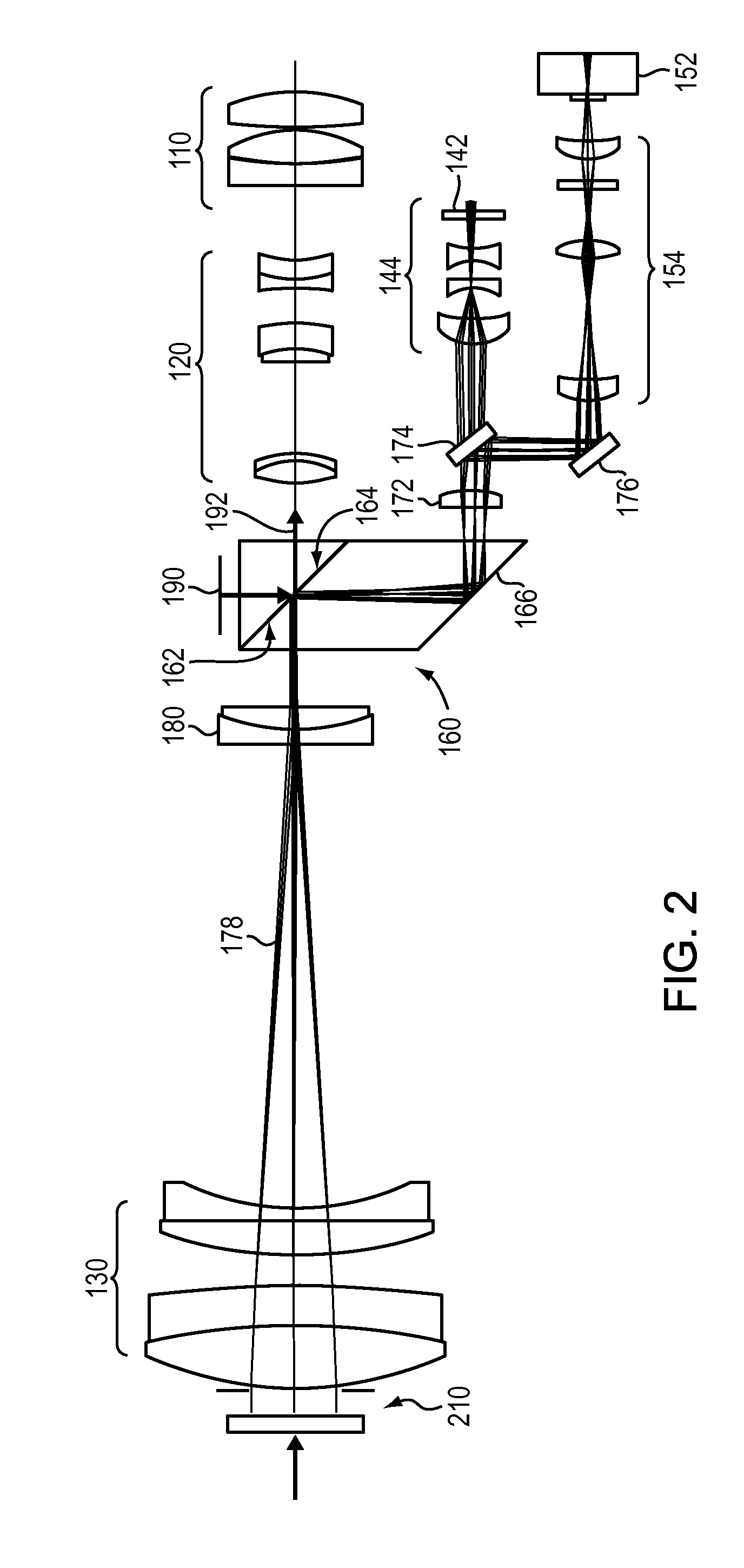
[0017]Aspects and embodiments are directed to an optical device, for example, a rifle sight or weapon scope, having integrated reticle and information displays and a laser rangefinder, which is compact and provides a flexible mechanism for maintaining alignment of the multiple devices as ballistic adjustments are made. According to certain embodiments, the optical device that has the capability to keep displayed imagery and a laser aligned with a scene as the field of view of the optical device is moved or adjusted. In one embodiment, the optical device allows a laser that is aligned to the scene and reticle to be adjusted as a group. This allows adjustments outside the original field of view while maintaining original alignment between the laser, scene, and reticle. In addition, according to certain embodiments, as the optical device changes magnification, the displayed image and fixed reticle maintain relative magnification to an operator's eye. Thus, the displayed imagery may mai...


PUM


Abstract

A direct view optical sight including an integrated laser rangefinder. One example of the sight includes an eyepiece, an objective providing an optical aperture and configured to direct electromagnetic radiation from a viewed scene to the eyepiece, an erector tube assembly coupled between the eyepiece and the objective, the laser rangefinder configured to transmit and receive laser radiation, and a beam combiner assembly mounted to the erector tube assembly and positioned between the erector tube assembly and the objective, the beam combiner assembly configured to combine the laser radiation and the electromagnetic radiation to allow the laser rangefinder to transmit and receive the laser radiation via the optical aperture of the objective, and to maintain optical alignment of the laser rangefinder and the viewed scene during movement of the erector tube assembly.

Description

CROSS-REFERENCE TO RELATED APPLICATIONS[0001]This application claims priority to and the benefit of co-pending U.S. Provisional Application No. 61 / 733,673 titled “MULTI-SPECTRAL BEAM COMBINING ZOOM ASSEMBLY” and filed on Dec. 5, 2012, which is herein incorporated by reference in its entirety.FEDERALLY SPONSORED RESEARCH[0002]This invention was made with U.S. government support under Grant No. W91CRB-10-R-0056 awarded by the U.S. Army. The U.S. government has certain rights in this invention.BACKGROUND[0003]It is difficult to keep tight alignment between an object scene and laser rangefinders or laser designators while making adjustments such as moving a reticle during bore-sighting or weapon zeroing. For example, when range to a target is found using the laser rangefinder and the ballistic adjustment is made, for targets at longer ranges the vertical change for the ballistic path and the laser path diverge, resulting in the laser aiming point moving out of the sight field of view. I...

Claims


Application Information

Patent Timeline
Patent Type & Authority Applications(United States)
IPC IPC(8): G02B23/04G02B27/01G02B5/20F41G3/06G02B7/00G01C3/08F41H5/20G02B27/10G02B25/00
CPCF41G3/065F41G1/38F41G1/473F41G3/06G02B27/0189G02B7/003G02B23/04G02B27/108G02B5/20G01C3/08F41H5/20G02B25/001
Inventor WATERMAN, MICHAELCHIPPER, ROBERT B.ISLAS, GILBERT J.MCINTOSH, JIM A.STALELY, III, JOHN R.FLORENCE, JAMES M.
Owner RAYTHEON CO
Why Eureka
Try Eureka