Method and apparatus for maintaining optical alignment for free-space optical communication

a free-space optical communication and optical alignment technology, applied in the field of free-space optical communication, can solve the problems of physical installation of optical conductors, and achieve the effect of maintaining optical alignment and maximizing the first receive power

Inactive Publication Date: 2006-10-10
SIGNIFY HLDG BV
View PDF25 Cites 43 Cited by
  • Summary
  • Abstract
  • Description
  • Claims
  • Application Information

AI Technical Summary

Benefits of technology

[0009]The present invention advantageously addresses the needs above as well as other needs by providing a system and method for use in free-space optical communication. The present invention additionally provides a method and apparatus for use in maintaining optical alignment in free-space optical communication. In one embodiment, the method for use in free-space optical communication comprises the steps of receiving a receive optical beam through a narrow field of view at a first position; determining a receive power level of the receive optical beam; shifting an alignment from the first position; detecting a change in receive power level; altering the shifting of the alignment to compensate for a decrease in the receive power level; and transmitting a transmit optical beam along the alignment, wherein the narrow field of view is less than a divergence of the transmit optical beam.
[0010]In another embodiment, the invention provides a method for use in optically communicating over free-space, comprising the steps of receiving a receive optical beam through a narrow field of view at a first position; determining a first receive power level of the receive optical beam; shifting an alignment; maximizing the first receive power; and transmitting a transmit optical beam along the alignment, wherein the narrow field of view is less than a divergence of the transmit optical beam. The narrow field of view can further be a narrow region of a multi-region field of view.
[0011]In another embodiment, the invention provides an apparatus for use in providing free-space optical communication, comprising a optical beam transmitter configured to generate a narrow diverging transmit beam; a narrow field of view optical receiver, wherein the field of view is less than the divergence of the transmit beam; and a controller coupled with the optical receiver, wherein the controller is configured to determine a power level of a receive beam and further configured to determine adjustments to a direction of transmission such that a maximum receive power is detected.
[0012]In another embodiment, the invention provides a method for use in optically communicating over free-space, comprising shifting an alignment of a link head; detecting a first maximum power level; determining a first alignment positioning of the link head when the first maximum power level is detected; recording the first alignment positioning when the first maximum power level is detected; and determining a first optimal alignment based at least in part on the recorded first alignment positioning.

Problems solved by technology

A major disadvantage of fiber optic conductors, however, is that they must be physically installed.

Method used


Image

  • Method and apparatus for maintaining optical alignment for free-space optical communication
  • Method and apparatus for maintaining optical alignment for free-space optical communication
  • Method and apparatus for maintaining optical alignment for free-space optical communication

Examples


Embodiment Construction

[0027]The following description is not to be taken in a limiting sense, but is made merely for the purpose of describing the general principles of the invention. The scope of the invention should be determined with reference to the claims.

[0028]A free space optical network is one in which high-speed network connectivity is achieved by modulating data onto a laser optical carrier and transmitting the optical information through free space to a receiver at some distance away. Free space networks provide communication at data-rates that are comparable to fiber optics data-rates while avoiding the cost and time associated with installing fiber-optic cabling.

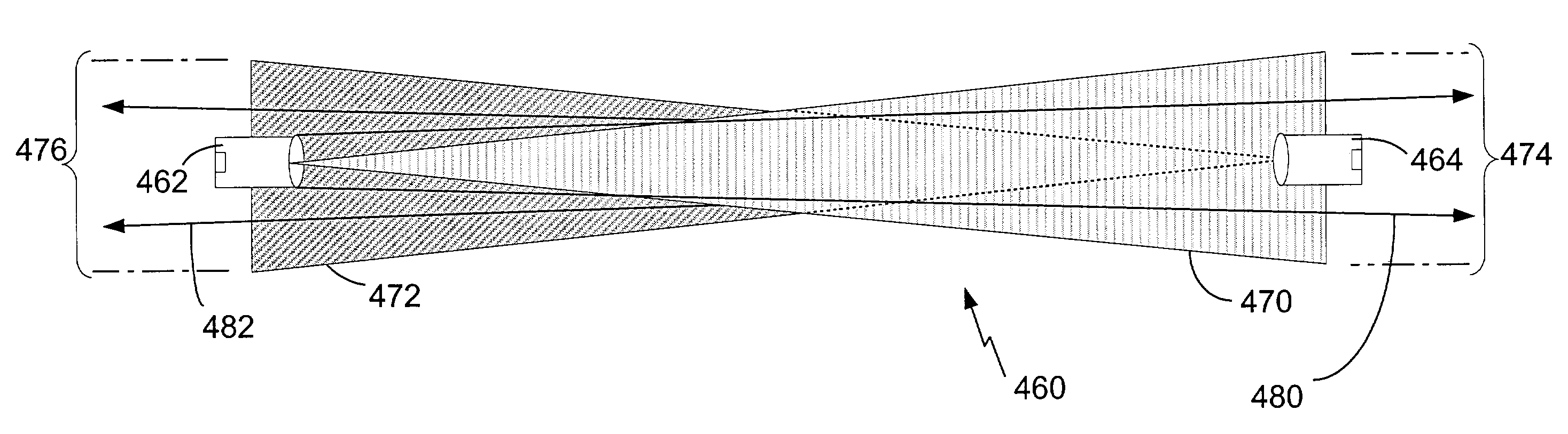
[0029]FIG. 1 depicts a free-space optical communication network 102 according to one embodiment of the present invention. The network includes a plurality of link heads 104. Each link head comprises a transmitter, a receiver or both a transmitter and receiver (i.e., a transceiver). A link head 104 is optically aligned with at least o...


PUM


Abstract

The present invention provides a method and apparatus for free-space optical communication. The method comprises the steps of receiving a receive optical beam through a narrow field of view, determining a receive power level, shifting an alignment, maximizing the receive power, and transmitting a transmit optical beam along the alignment, wherein the narrow field of view is less than a divergence of the transmit optical beam. The narrow field of view can be a narrow region of a multi-region field of view. The apparatus comprises an optical beam transmitter configured to generate a narrow diverging transmit beam, a narrow field of view optical receiver, wherein the field of view is less than the divergence of the transmit beam, and a controller configured to determine a power level of a receive beam and to determine adjustments to a direction of transmission maximizing receive power.

Description

BACKGROUND OF THE INVENTION[0001]1. Field of the Invention[0002]The present invention relates generally to free-space optical communication, and more specifically to alignment tracking control in free-space optical networks.[0003]2. Discussion of the Related Art[0004]For digital data communications, optical media offers many advantages compared to wired and RF media. Large amounts of information can be encoded into optical signals, and the optical signals are not subject to many of the interference and noise problems that adversely influence wired electrical communications and RF broadcasts. Furthermore, optical techniques are theoretically capable of encoding up to three orders of magnitude more information than can be practically encoded onto wired electrical or broadcast RF communications, thus offering the advantage of carrying much more information.[0005]Fiber optics is the most prevalent type of conductors used to carry optical signals. An enormous amount of information can be...

Claims


Application Information

Patent Timeline
Patent Type & Authority Patents(United States)
IPC IPC(8): H04B10/00H04B10/10
CPCH04B10/1127
Inventor ANDREU-VON EUW, CHRISTIANNEFF, BRIAN W.OSCOLAI, CATHALMULLER, OLAF
Owner SIGNIFY HLDG BV
Why Eureka
Try Eureka