Log analysis system, fault cause analysis system, log analysis method, and recording medium which stores program

a technology of log analysis and fault cause analysis, applied in the field of log analysis of information processing system, can solve problems such as the difficulty of administrator to analyze the entire log in detail

Active Publication Date: 2016-08-04
NEC CORP
View PDF2 Cites 12 Cited by
  • Summary
  • Abstract
  • Description
  • Claims
  • Application Information

AI Technical Summary

Benefits of technology

[0021]According to the present invention, it is possible to appropriately extract, or assist in extracting, a normal operation p

Problems solved by technology

However, since a log output by the information processing system is huge,

Method used


Image

  • Log analysis system, fault cause analysis system, log analysis method, and recording medium which stores program
  • Log analysis system, fault cause analysis system, log analysis method, and recording medium which stores program
  • Log analysis system, fault cause analysis system, log analysis method, and recording medium which stores program

Examples


concrete example 1

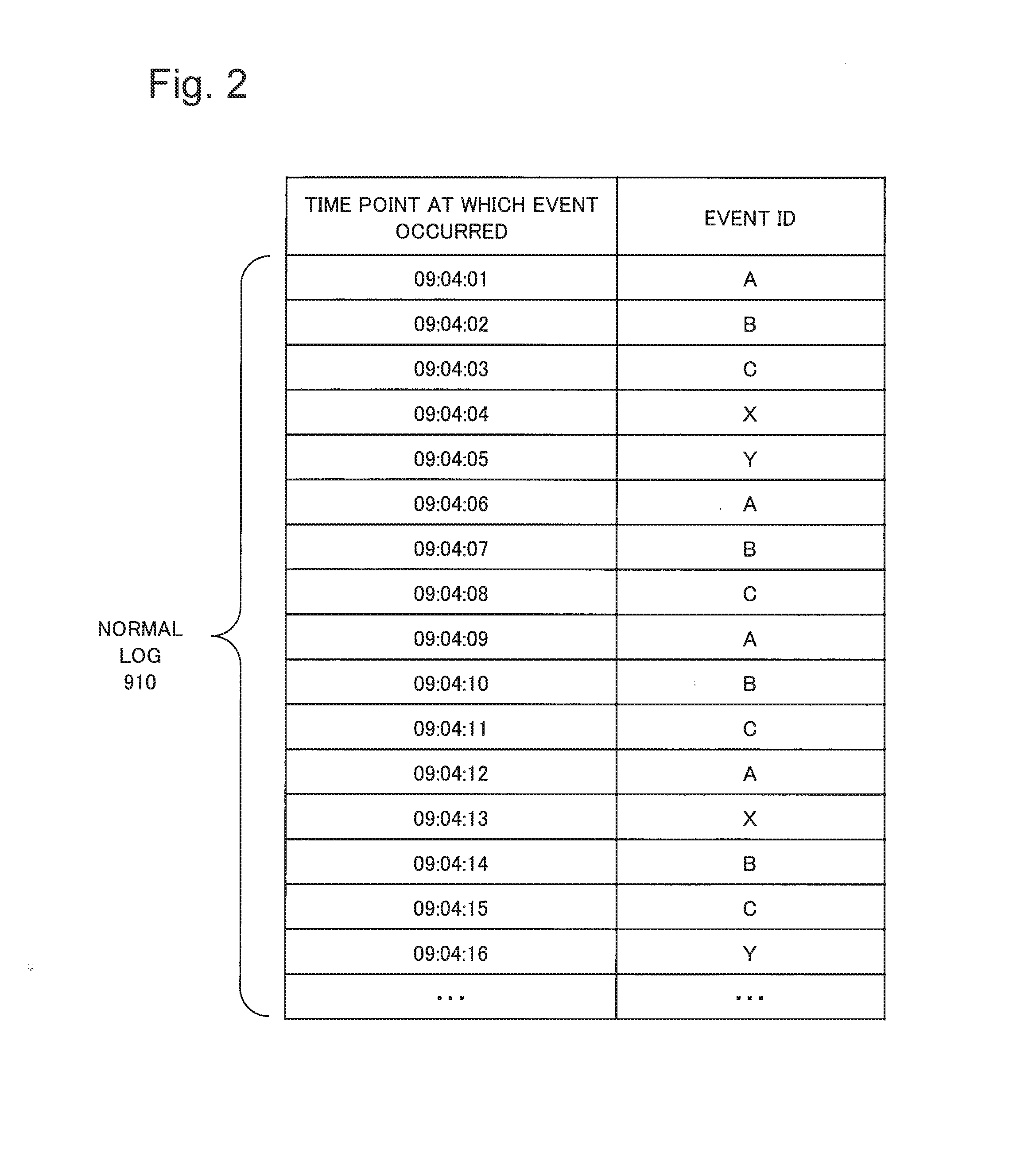
[0082]The selection unit 130 analyzes the parent-child relationship for each of the plurality of patterns. As a result of the analysis by the selection unit 130, the parent-child relationship indicating that the parent pattern is “ABCX”, the child pattern is “ABC”, and the grandchild pattern is “AB”, or the like is obtained for the pattern “ABCX”, for example.

[0083]The selection unit 130 calculates the ratio of a frequency of a child pattern to a frequency of a parent pattern. In the example presented in FIG. 5, the frequency of the parent pattern “ABCX” is 17, and the frequency of the child pattern “ABC” is 43; accordingly, the ratio between the frequencies is 43 / 17=2.5. Here “ / ” is a symbol representing division. When the ratio is a relatively large value (e.g., a case where the value is 2 or larger), there is a high possibility that the parent pattern is a “meaningless pattern”. This is because it is considered that such a parent pattern is a pattern of the child pattern to which...

concrete example 2

[0085]The selection unit 130 analyzes the parent-child relationship for each of the plurality of patterns. The selection unit 130 may preferentially select, as a “meaningful pattern”, a pattern which is formed with a large number of elements (events) and the frequency of which is high. For example, the pattern “ABC” may be preferentially selected as a “meaningful pattern” since the pattern “ABC” is formed with three elements (A, B, and C) and has a high frequency of 43. The criterion for determining whether the number of elements with which a pattern is formed is large or small and the criterion for determining whether a frequency is high or low may be set in advance, for example.

concrete example 3

[0086]The selection unit 130 analyzes the parent-child relationship for each of the plurality of patterns. FIG. 7 is a table obtained by analyzing, for each pattern, the number of parent patterns of a pattern. The selection unit 130 may preferentially select a child pattern having more parent patterns as a “meaningful pattern”.


PUM


Abstract

An objective of the present invention is to appropriately extract, or assist in extracting, a normal operation pattern from a normal operation log. A log file including information wherein a plurality of log records is ordered in time series is segmented into a plurality of log groups according to prescribed rules. A plurality of patterns which are configured by a plurality of events which are contiguous in time series is extracted from the plurality of log groups, and the patterns are associated with frequency information which represents how many log records the pattern is extracted from. The pattern to be outputted from the plurality of patterns is selected on the basis of an inclusion relation between the plurality of events which are contiguous in time series and configure a given pattern and the plurality of events which are contiguous in time series and configure other patterns, and on the basis of the frequency information which is associated with the patterns.

Description

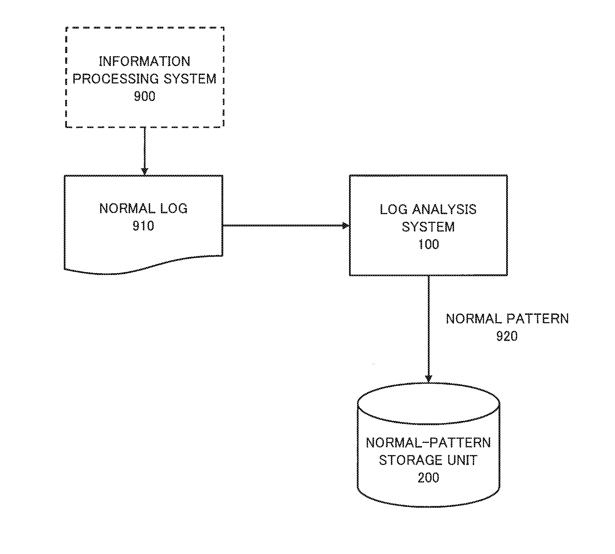
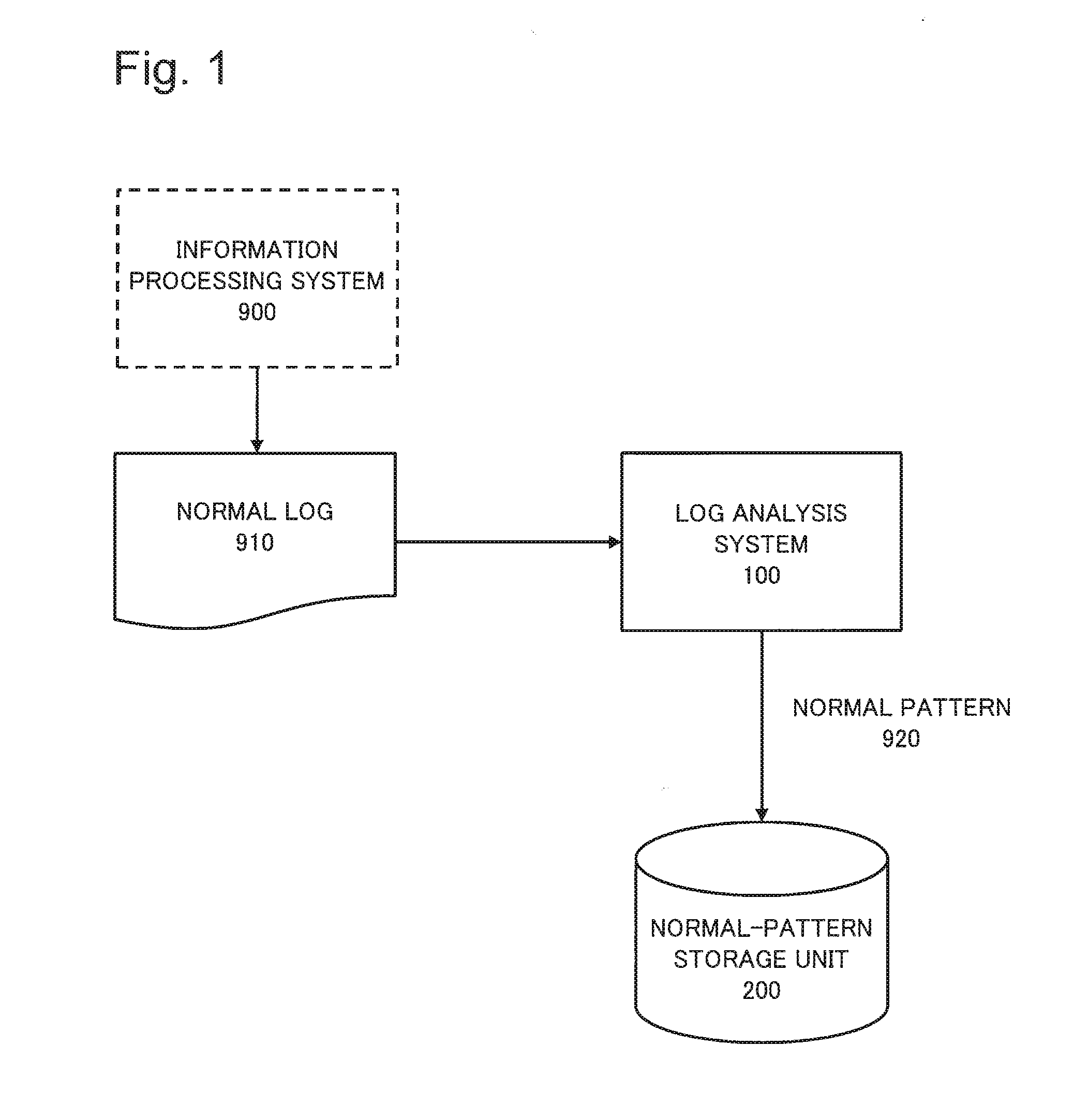
TECHNICAL FIELD[0001]The present invention relates to a technology of analyzing a log output by an information processing system.BACKGROUND ART[0002]For management and maintenance of an information processing system, a person who is in charge of the management and maintenance (to be referred to as “administrator” below) needs to identify, when a fault occurs in the information processing system, a cause of the fault. A log output by the information processing system may become an important clue when the administrator identifies the cause of the fault. However, since a log output by the information processing system is huge, it is difficult for the administrator to analyze the entire log in detail.[0003]For the above reason, to identify the cause of the fault, the administrator needs to identify a message indicating a direct or indirect cause of occurrence of the fault (referred to as “cause message” below) from the huge amount of log output by the information processing system. Then...

Claims


Application Information

Patent Timeline
IPC IPC(8): G06F11/07
CPCG06F11/0778G06F11/079
Inventor TOGAWA, RYOSUKE
Owner NEC CORP
Why Eureka
Try Eureka