
Occlusion handling for computer vision

a computer vision and object technology, applied in image analysis, image enhancement, instruments, etc., can solve problems such as system failure, system failure, and system failure, and achieve the effect of avoiding system failure, avoiding system failure, and avoiding system failur

Active Publication Date: 2016-08-04
QUALCOMM INC
View PDF0 Cites 36 Cited by
  • Summary
  • Abstract
  • Description
  • Claims
  • Application Information

AI Technical Summary

Benefits of technology

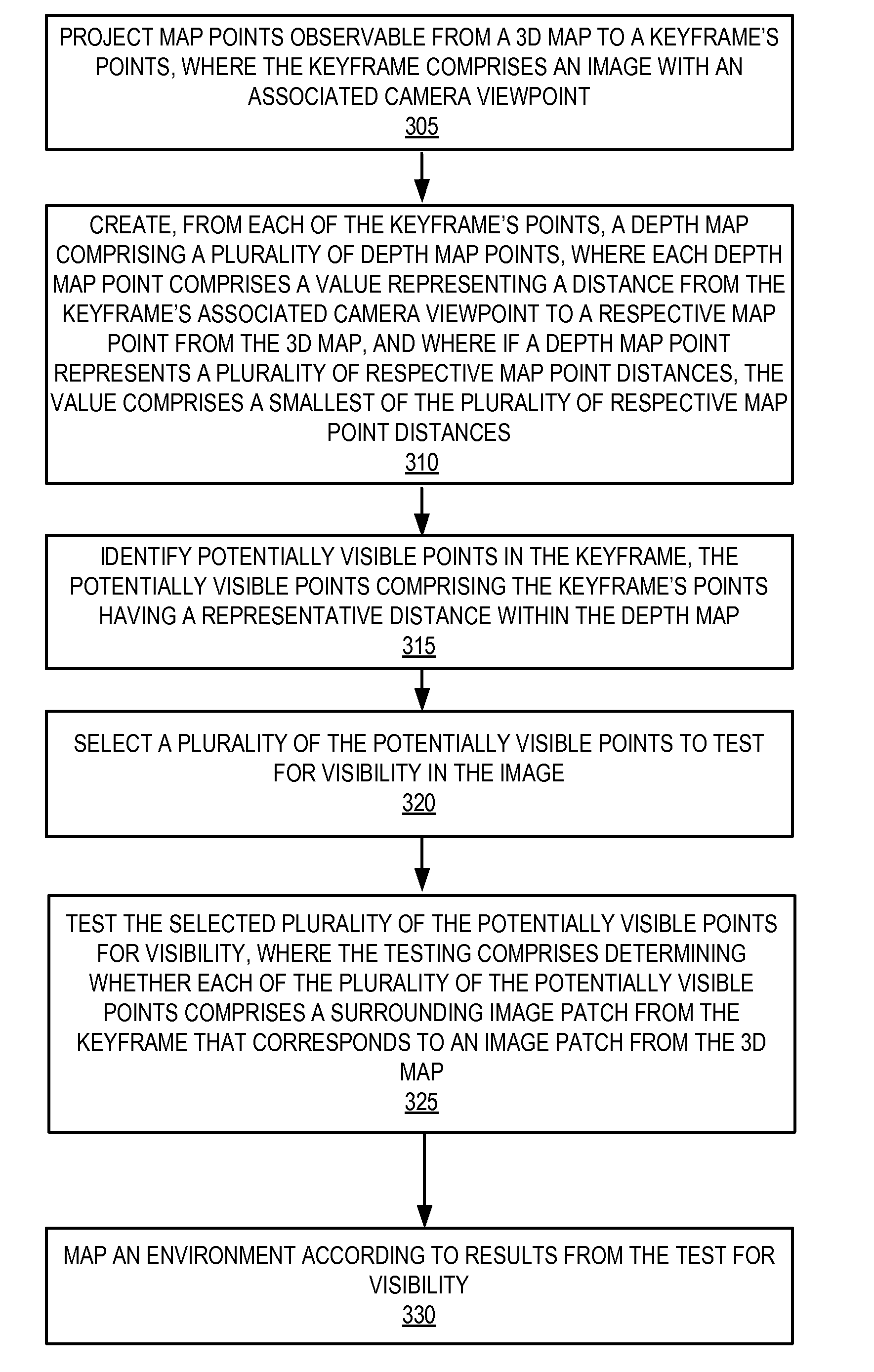
The patent describes a method and apparatus for handling occlusion in computer vision. The method involves projecting map points from a 3D map to points in a keyframe, creating a depth map with a plurality of depth map points, identifying potentially visible points in the keyframe, and testing these points for visibility. The testing involves determining whether each point has a surrounding image patch that corresponds to an image patch from the 3D map. The apparatus includes a device with instructions to perform these steps. The technical effect of this patent is to improve the accuracy and efficiency of computer vision systems by handling occlusion and creating a more accurate representation of the environment.

Problems solved by technology

However, when a new (un-mapped) object occludes an existing 3D model, SLAM systems may produce errors as the SLAM system attempts to track the pre-existing / reconstructed 3D model behind the new occluding object.
Errors can occur when the SLAM system attempts to track features of the 3D model because the features occluded by the new object can no longer be tracked by the SLAM system.
In some cases, occlusion errors cause SLAM systems to fail in tracking the 3D model and the occluding object is not reconstructed.
Eliminating the tracking errors that occur from the new object occlusion typically requires extensive processing of the scene beyond what may be possible in real time on certain devices (e.g., limited processing capability portable or mobile devices).

Method used


Image

  • Occlusion handling for computer vision
  • Occlusion handling for computer vision
  • Occlusion handling for computer vision

Examples


Embodiment Construction

[0026]The word “exemplary” or “example” is used herein to mean “serving as an example, instance, or illustration.” Any aspect or embodiment described herein as “exemplary” or as an “example” is not necessarily to be construed as preferred or advantageous over other aspects or embodiments.

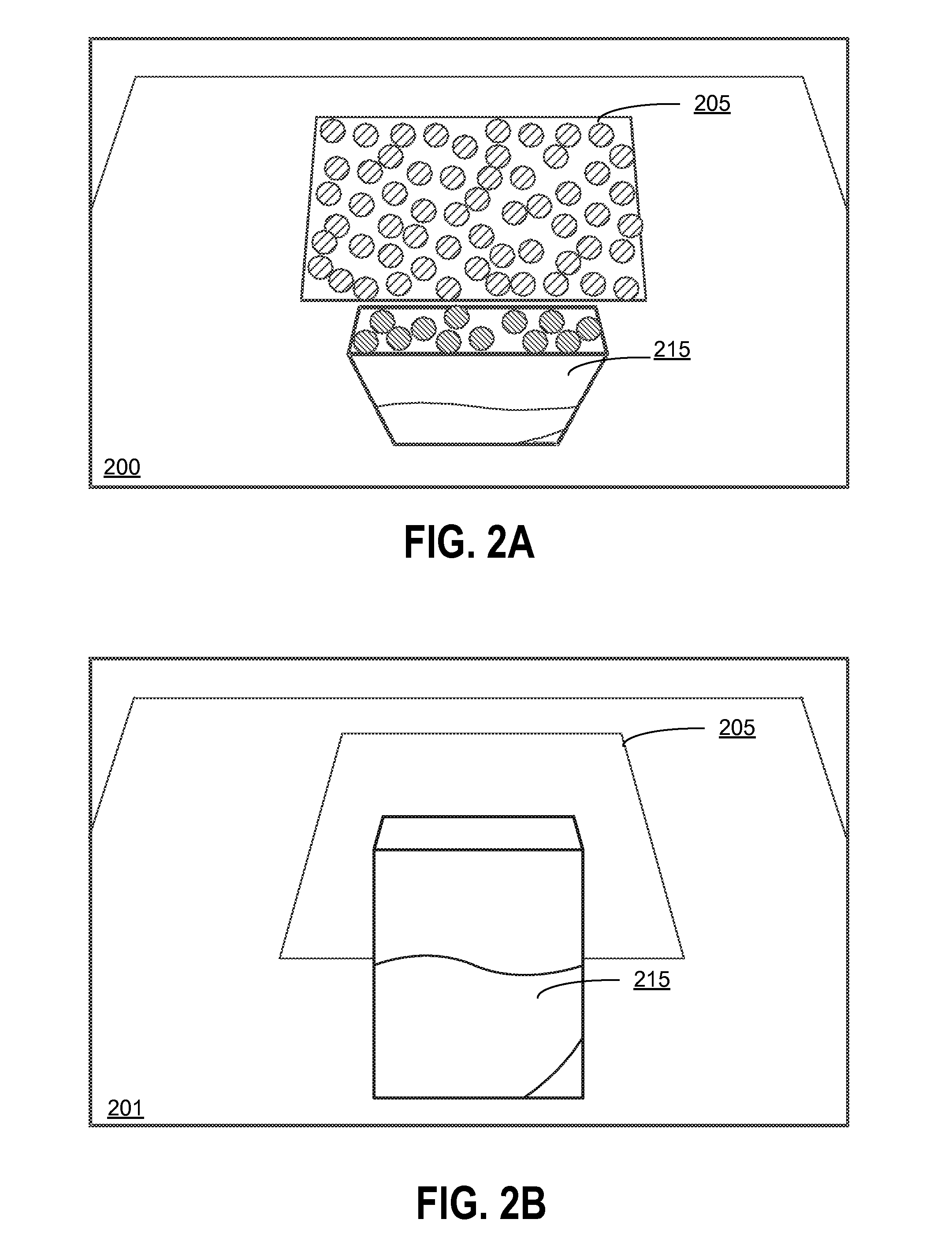
[0027]In one embodiment, Occlusion Handling for Computer Vision (described herein as “OHCV”) filters occluded map points with a depth-map and determines visibility of a subset of points. 3D points in a 3D map have a known depth value (e.g., as a result of Simultaneous Localization and Mapping (SLAM) or other mapping method). In one embodiment, OHCV compares depth of 3D points to depths for equivalent points (e.g., points occupying a same position relative to the camera viewpoint) in a depth mask / map. In response to comparing two or more equivalent points, points with a greater depth (e.g., points farther away from the camera position) are classified as occluded. Points without a corresponding depth ...


PUM


Abstract

Disclosed are a system, apparatus, and method for performing occlusion handling for simultaneous localization and mapping. Occluded map points may be detected according to a depth-mask created according to an image keyframe. Dividing a scene into sections may optimize the depth-mask. Size of depth-mask points may be adjusted according to intensity. Visibility may be verified with an optimized subset of possible map points. Visibility may be propagated to nearby points in response to determining an initial visibility of a first point's surrounding image patch. Visibility may also be organized and optimized according to a grid.

Description

FIELD[0001]The subject matter disclosed herein relates generally to occluded objects and environment detection in computer vision.BACKGROUND[0002]Computer vision is a field that includes methods and systems for acquiring, analyzing, processing, and understanding images (e.g., real world image captures) to provide an event or result. For example, one computer vision technique is Simultaneous Localization and Mapping (SLAM), which can process the input of a single camera and continuously build up a three dimensional (3D) model (e.g., reconstructed map) of an environment as the camera moves in Six Degrees of Freedom (6DOF). SLAM systems can simultaneously track the pose of the camera with respect to the 3D model while mapping the 3D model. However, when a new (un-mapped) object occludes an existing 3D model, SLAM systems may produce errors as the SLAM system attempts to track the pre-existing / reconstructed 3D model behind the new occluding object. Errors can occur when the SLAM system ...

Claims


Application Information

Patent Timeline
IPC IPC(8): G06K9/46G06T7/00G06T7/60G06K9/00
CPCG06K9/00624G06K9/46G06K2009/4666G06T2207/10028G06T7/60G06T2207/20021G06T7/2033G06T7/0051G06T7/246G06T7/50
Inventor PARK, YOUNGMINWAGNER, DANIEL
Owner QUALCOMM INC
Learn More