Belay descender device on a rope with gearing-down and Anti-panic blocking

a technology of descending device and rope, which is applied in the direction of life-saving device, mountaineering, sport apparatus, etc., can solve the problem that the user will not be able to stop to the detriment of his safety

Active Publication Date: 2016-08-11
ZEDEL CORP
View PDF8 Cites 20 Cited by
  • Summary
  • Abstract
  • Description
  • Claims
  • Application Information

AI Technical Summary

Benefits of technology

[0008]The object of the invention consists in providing a belay descender device on a rope that is able to be easily unlocked manually to improve the fluidity of descent along the rope, and that benefits from an automatic re-locking function in the event of the user panicking.

Problems solved by technology

The rope is free and the user will not be able to stop to the detriment of his safety.

Method used


Image

  • Belay descender device on a rope with gearing-down and Anti-panic blocking
  • Belay descender device on a rope with gearing-down and Anti-panic blocking
  • Belay descender device on a rope with gearing-down and Anti-panic blocking

Examples


Embodiment Construction

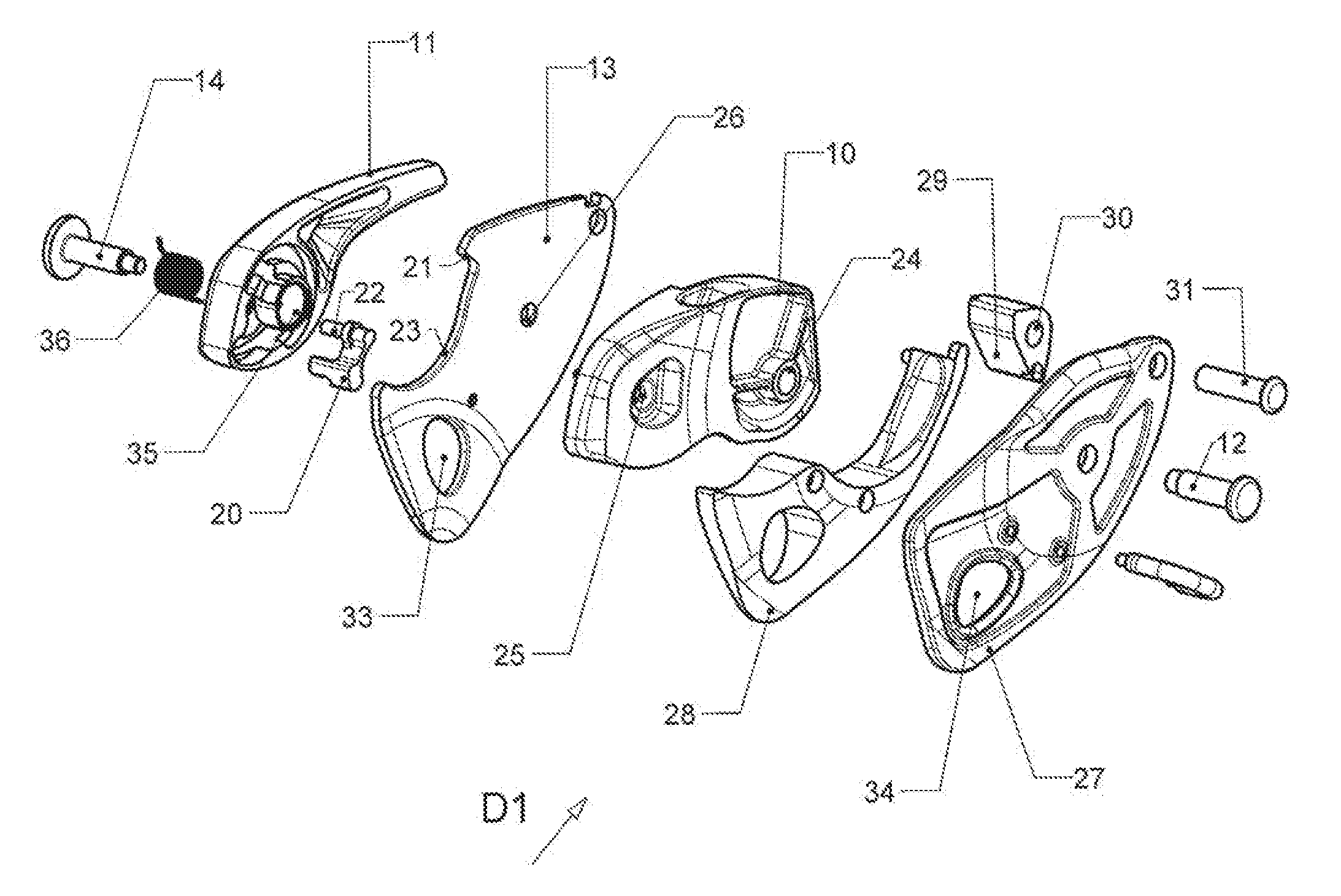
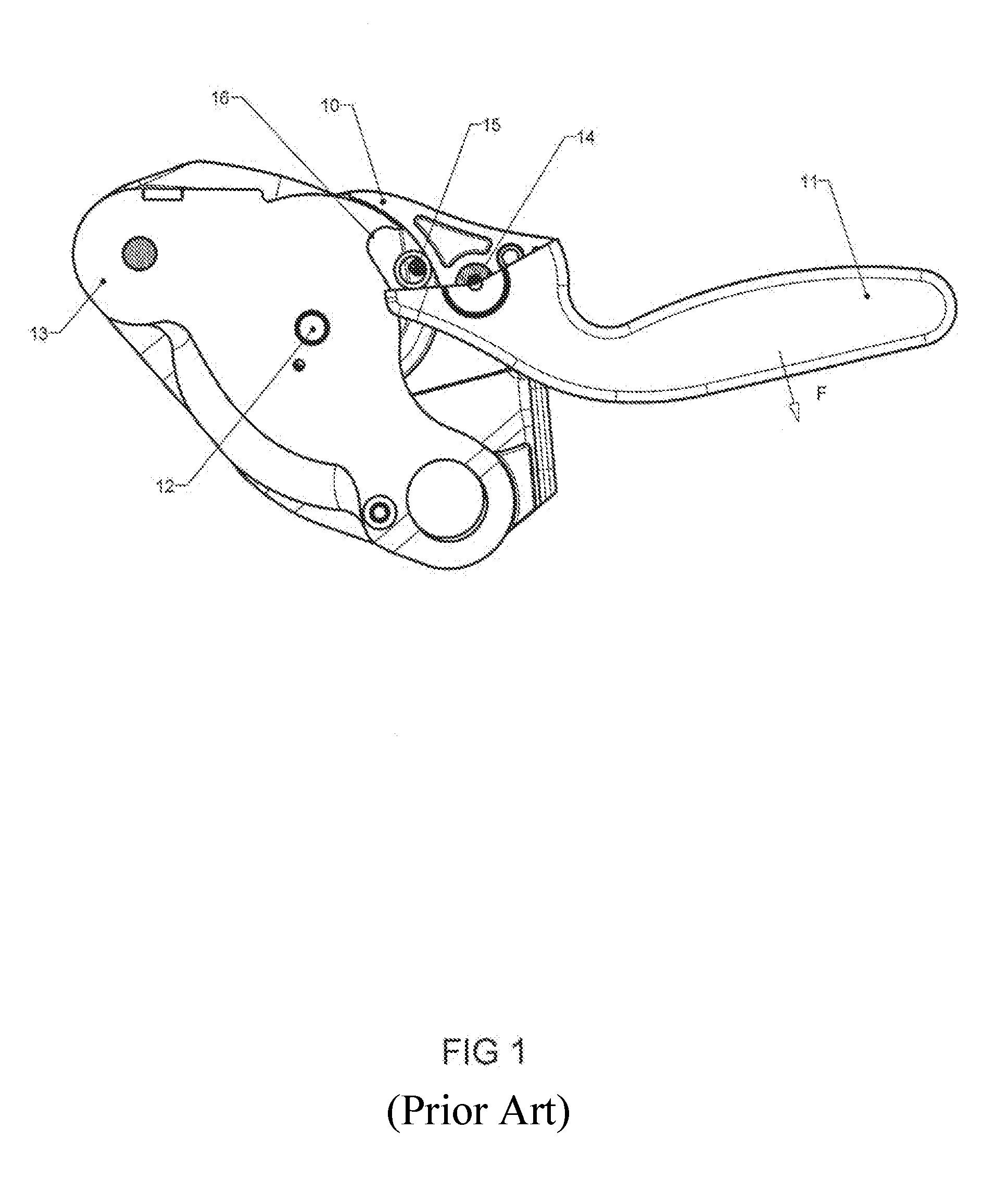
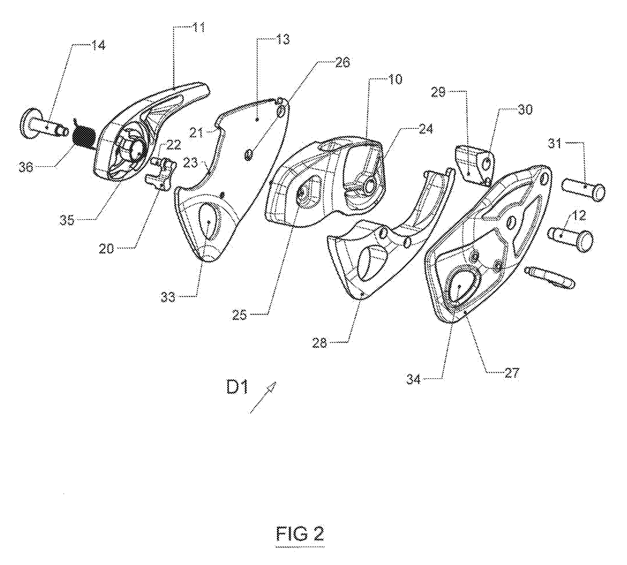
[0026]With reference to FIG. 2 illustrating an exploded perspective view of a first belay descender D1 according to the invention, the fixed flange 13 for fitting the rotary cam 10 and the operating lever 11 in the form of a handle articulated on the cam 10 by the pivot-pin 14 can be seen. The cam 10 and operating lever 11 are arranged on each side of the flange 13. The bearing pin 15 of the device of FIG. 1 of the prior art is replaced by a drive rod 20, and the direct stop 16 is not provided and is replaced by a guide ramp 21 located along the edge of the flange 13. The rod 20 is articulated on the lever 11 by means of a pivot-pin 22, and is kept in position by a spring (not shown). The flange 13 is provided with a recess 23 allowing passage of the rod 20 when if moves along the guide ramp 21 after actuation of the lever 11 in the unlocking direction. The recess 23 is delineated at its top part by the guide ramp 21. The cam 10 comprises a first aperture 24 for passage of the pivot...


PUM


Abstract

A belay descender device for a rope comprising a earn mounted rotating on a fixed flange to perform locking of the rope when said rope is under tension, and a lever articulated on the cam to perform progressive unlocking of the rope with a geared-down effect at the beginning of unlocking travel of the lever. The operating lever comprises transmission means collaborating with a guide ramp of the flange to interrupt the mechanical link with the cam after an intermediate position of the lever has been passed resulting in freeing from said ramp outside the gearing-down area. The end of the guide ramp of the flange corresponds to the anti-panic position of the transmission means, enabling automatic locking of the canvas soon as the gearing-down area has been passed.

Description

BACKGROUND OF THE INVENTION[0001]The invention relates to a belay descender device for a rope comprising:[0002]a cam mounted rotating on a fixed flange to perform locking of the rope when said rope is under tension,[0003]an operating lever or handle articulated on the cam to cause progressive unlocking of the rope with a geared-down effect at the beginning of the unlocking travel of the lever.[0004]STATE OF THE ART[0005]FIG. 1 represents a self-locking delay device for a rope described In detail in the document EP 2301631. It comprises a pulley in the form of a cam 10 arranged to cause locking of the rope when the rope is under tension, and an operating lever 11 collaborating with the cam 10 in order to cause progressive unlocking of the rope following a manual action on the lever 11 in the direction of the arrow F. The lever 11 acts on the cam 10 respectively with a geared-down effect In an initial part of its unlocking travel and with a direct driving effect in a final part of its...

Claims


Application Information

Patent Timeline
Patent Type & Authority Applications(United States)
IPC IPC(8): A62B1/14
CPCA63B29/02A62B1/14A62B1/10
Inventor CHAUMONTET, MICHAELMOINE, JULIENQUILLARD, CHRISTOPHE
Owner ZEDEL CORP
Why Eureka
Try Eureka