
Handheld Fluid Container

a fluid container and hand-held technology, applied in the direction of cans/barrels/drums, cans/barrels/drums, packaging, etc., can solve the problems of unbalanced container weight and contents, fatigue and injury, etc., to reduce stress and fatigue, reduce torque, and reduce hand and wrist fatigue

Active Publication Date: 2016-08-11
BAJUYO ANTONIO
View PDF9 Cites 7 Cited by
  • Summary
  • Abstract
  • Description
  • Claims
  • Application Information

AI Technical Summary

Benefits of technology

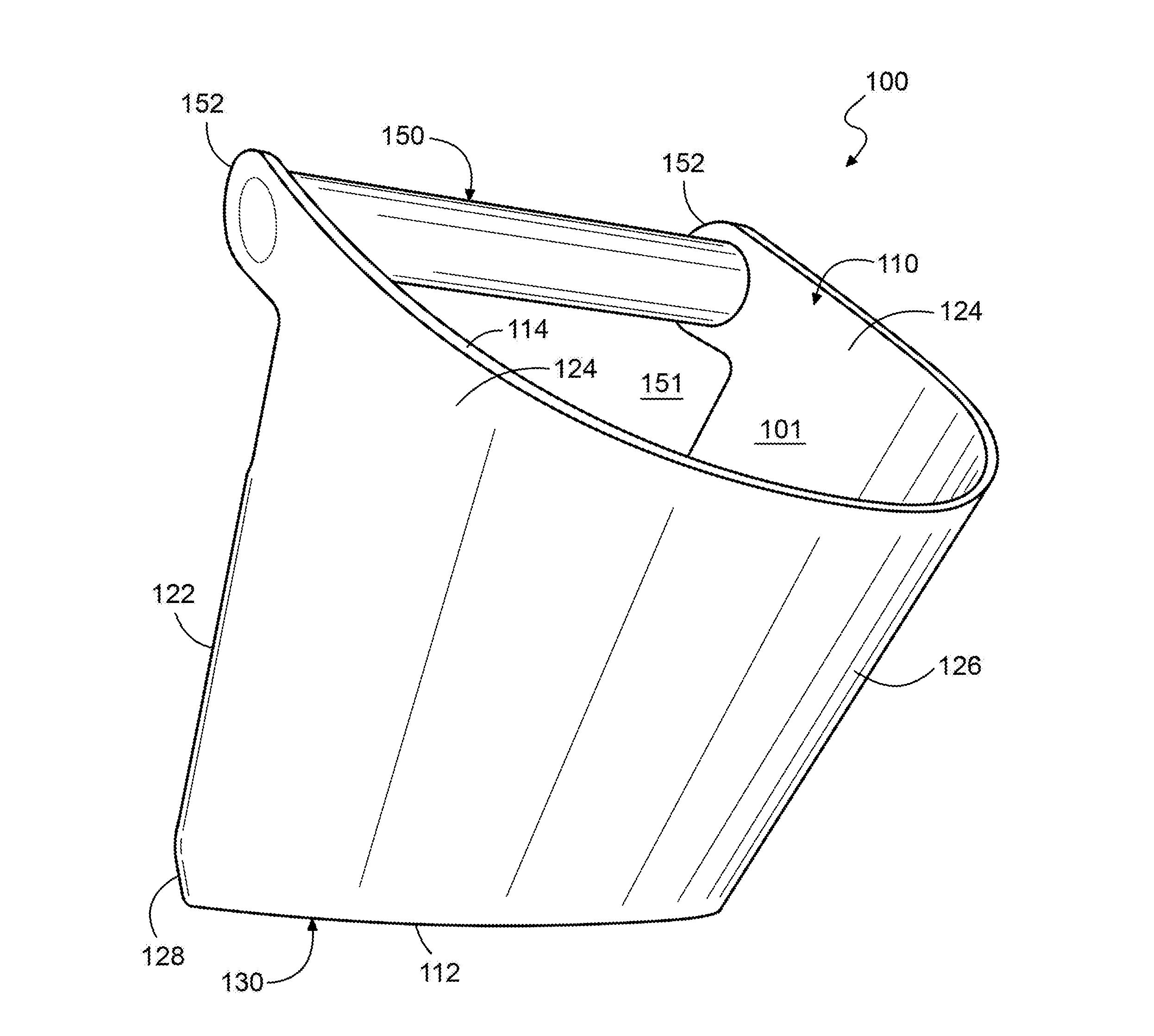
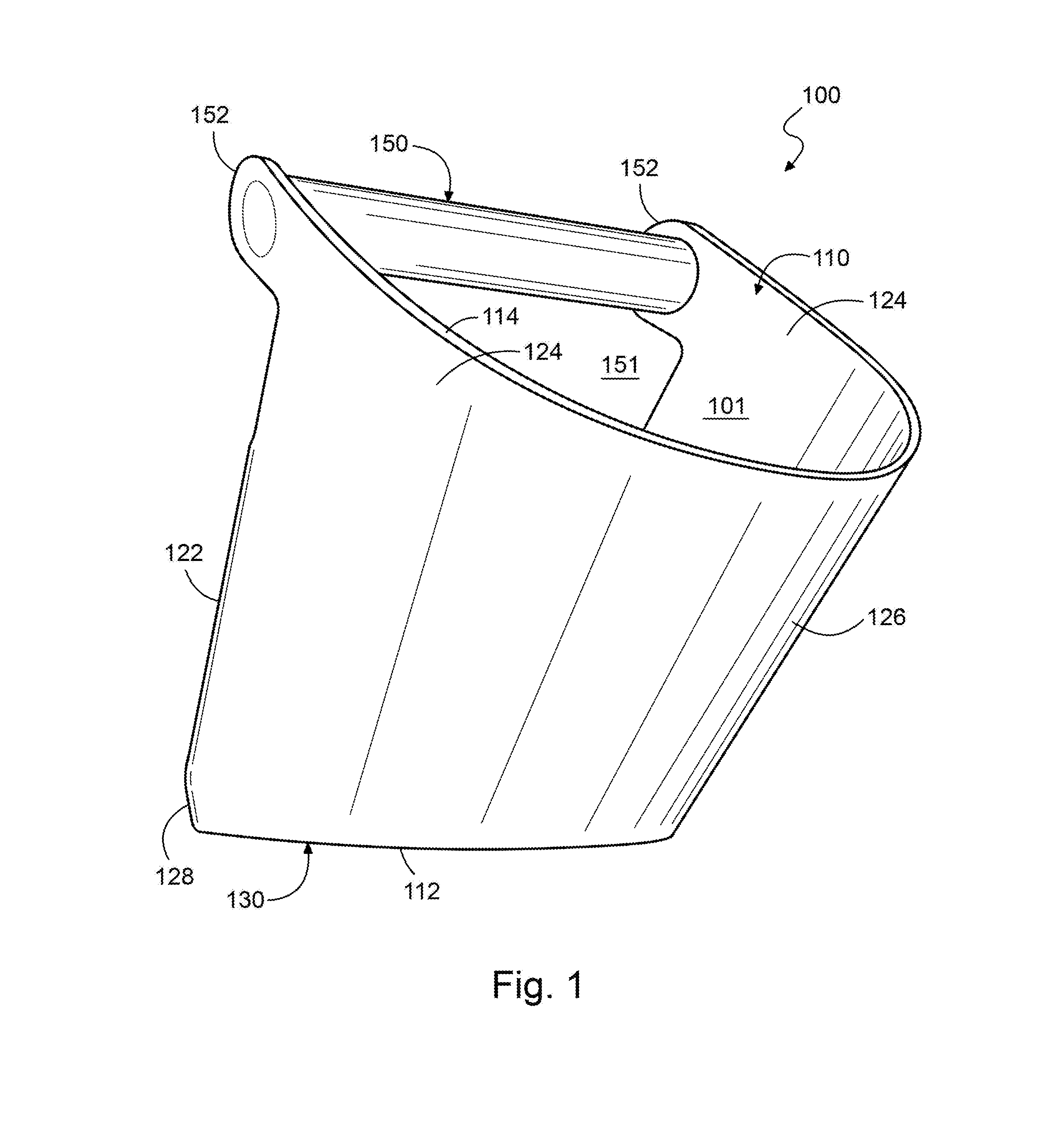
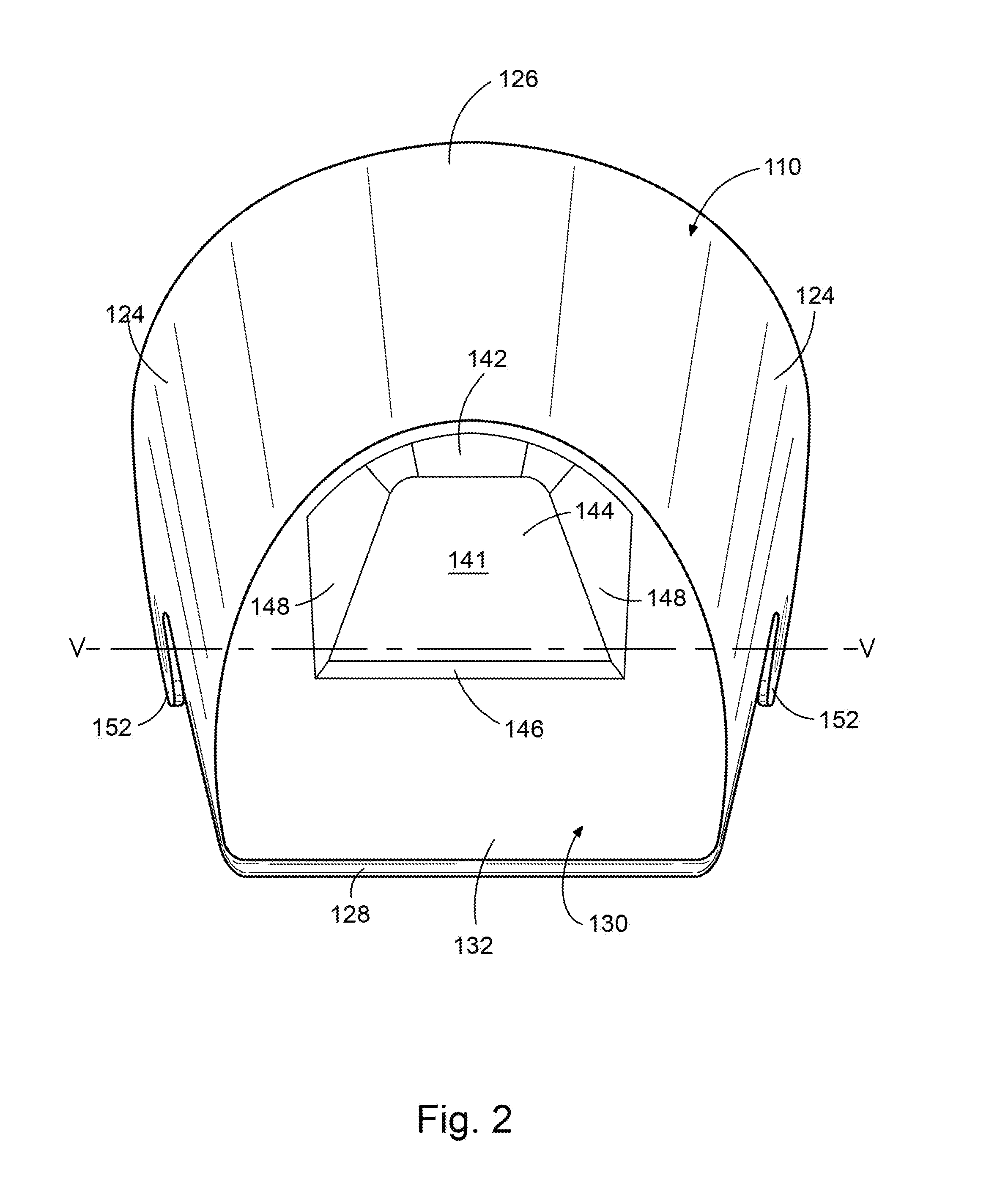
This patent is about a new type of bottle that reduces the strain on your hands and wrists from carrying heavy fluids. The bottle has a unique design that puts the majority of the fluid volume at the back of the bottle, where it is held and supported by the user. This helps to shift the center of gravity of the bottle backward, reducing torque and stress on the user's hand. The front and rear walls of the bottle are angled forward, and the bottom of the bottle has a raised floor area or semielliptical shape to further decrease the interior volume. The bottle also has handle parts and openings that optimize its ergonomics, making it easier to hold and use. Overall, this new design of bottle helps improve the user experience when carrying fluids.

Problems solved by technology

Wire bails are convenient for carrying or toting the fluid containers, but often cumbersome for one handed support of the containers while conveniently accessing the contents of the containers.
When held other than over the container's center of gravity, the weight of the container and its contents is unbalanced and creates a torque that is born by the user's hand and wrist.
While holding fluid containers in such manners is often ideal for its particular use, the unbalanced weight of the fluid container is often uncomfortable for the user and leads to fatigue and injury over time and repetitive use.

Method used


Image

  • Handheld Fluid Container
  • Handheld Fluid Container
  • Handheld Fluid Container

Examples


Embodiment Construction

[0026]In the following detailed description of the preferred embodiments, reference is made to the accompanying drawings that form a part hereof, and in which is shown by way of illustration specific preferred embodiments in which the invention may be practiced. These embodiments are described in sufficient detail to enable those skilled in the art to practice the invention, and it is understood that other embodiments may be utilized and that logical, structural, mechanical, electrical, and chemical changes may be made without departing from the spirit or scope of the invention. To avoid detail not necessary to enable those skilled in the art to practice the invention, the description may omit certain information known to those skilled in the art. The following detailed description is, therefore, not to be taken in a limiting sense, and the scope of the present invention is defined only by the appended claims.

[0027]Referring now to the drawings, several different but exemplary embod...


PUM


Abstract

A handheld fluid container shaped and configured so that the majority of the fluid volume is carried near the rear of the container where the container is held and supported. In various embodiments, the containers have handle parts and / or handle openings that allow the containers to be manually supported from the rear of the containers. The container bodies also have forward angled front and rear walls and container bottoms shaped so that the majority of the interior volume of the container is located at the rear of the container rather than at the front. The center of gravity of the containers when partially or fully filled with fluid is located near the rear of the container where it is manually supported by the user.

Description

[0001]This application claims the benefit of U.S. Provisional Application No. 62 / 176,204 filed Feb. 11, 2015, the disclosure of which is hereby incorporated by reference.[0002]This invention relates to fluid containers and has specific relevance to handheld fluid containers.BACKGROUND OF INVENTION[0003]Handheld fluid containers, such as pails, buckets, paint cans and the like, are used in a variety of applications and generally well known in such arts. Often, handheld fluid containers have wire bails or types of grip handles. Wire bails are convenient for carrying or toting the fluid containers, but often cumbersome for one handed support of the containers while conveniently accessing the contents of the containers. Effort must be made to twist the bail away from the center, or the container must be grasped by a side wall or bottom.[0004]In many applications, such as painting, handheld fluid containers, i.e paint cans and pails, must be supported with one hand while the other hand a...

Claims


Application Information

Patent Timeline
Patent Type & Authority Applications(United States)
IPC IPC(8): B65D25/28B65D43/02
CPCB65D43/02B65D25/282B65D1/14B65D25/00B65D25/2888
Inventor BAJUYO, ANTONIO
Owner BAJUYO ANTONIO
Learn More