

Handheld power tool
a power tool and hand-held technology, applied in the field of hand-held power tools, can solve the problems of reduced wrist tiredness and reduced work efficiency, and achieve the effect of convenient operation
- Summary
- Abstract
- Description
- Claims
- Application Information
AI Technical Summary
Benefits of technology
Problems solved by technology
Method used
Image

Examples
Embodiment Construction
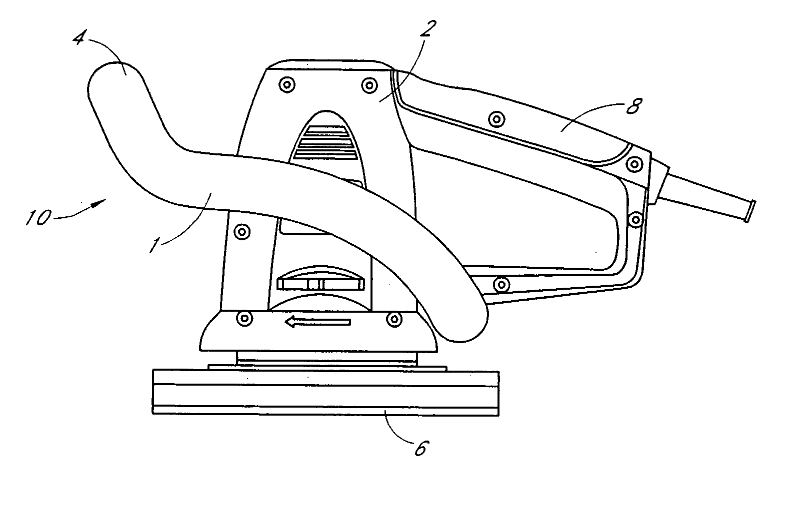
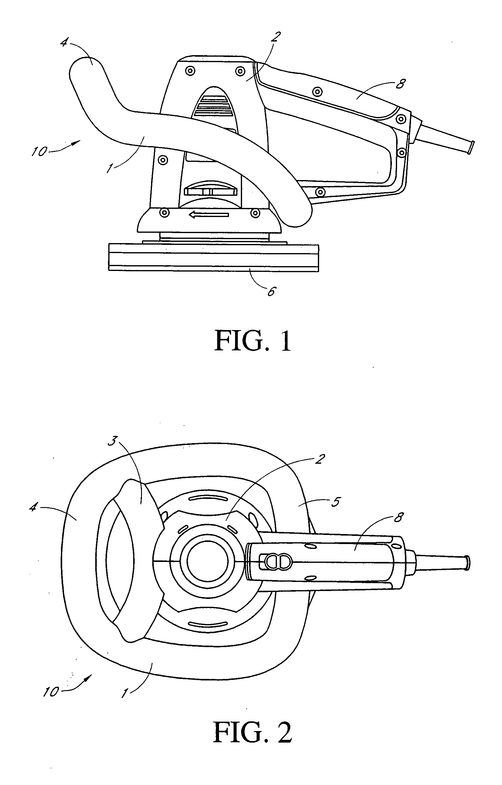
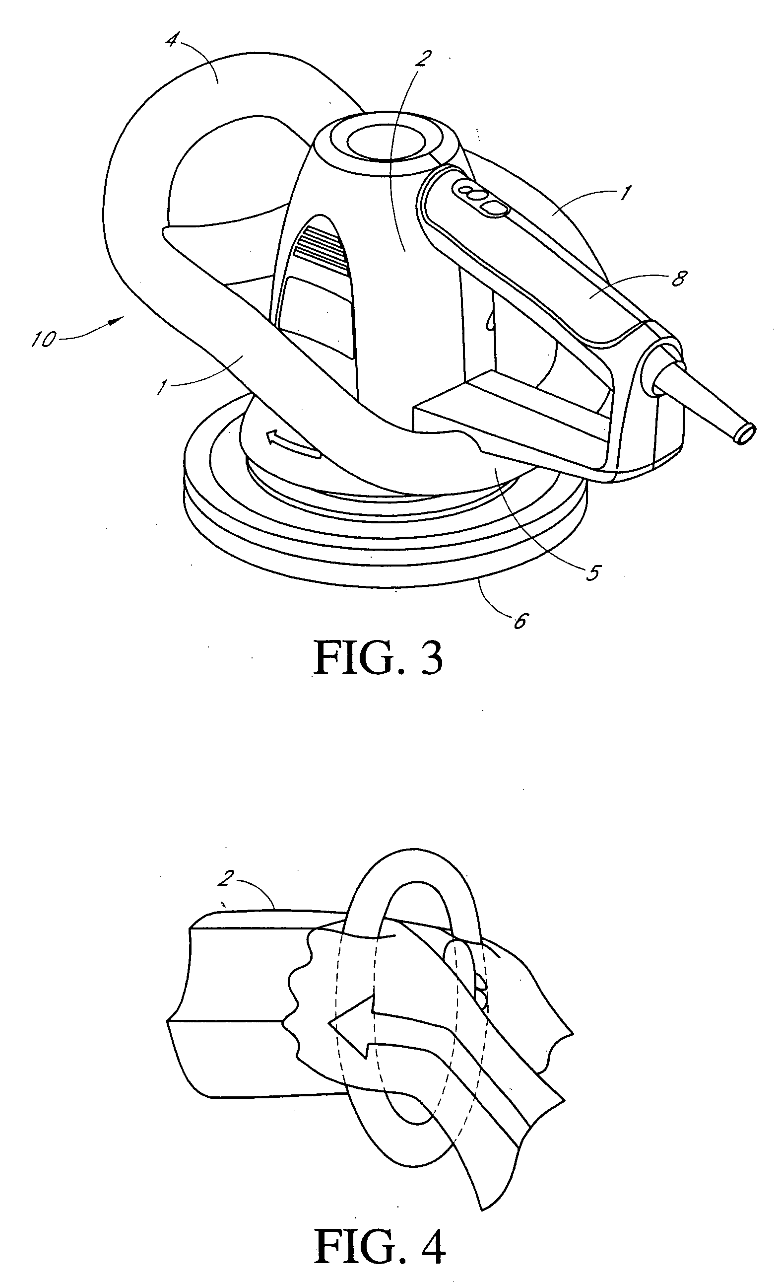
[0047] Referring to FIGS. 1 to 3, 5 and 7, an embodiment of the handheld power tool of the invention includes a main housing 2, a rear handle 8 which is mounted on the main housing 2 and an annular handle 10 which is connected to (and around) the main housing 2. The main housing 2 houses the driving mechanism and has a buffing member 6 in the basal plane. The rear handle 8 has a substantially C-shaped configuration and extends axially from the main housing 2.
[0048] The annular handle 10 is shown in isolation in FIG. 8 and comprises two oppositely disposed side handle members 1 and a front handle member 4 which joins the front end portions of the two oppositely disposed side handle members 1. The front end portions of the two oppositely disposed side handle members 1 are smoothly interconnected with the side end portions of the front handle member 4. The two oppositely disposed side handle members 1 are tilted gradually upwardly with respect to the basal plane from rear to front. Th...
PUM
 Abstract
Description
Claims
Application Information