Contact apparatus
- Summary
- Abstract
- Description
- Claims
- Application Information
AI Technical Summary
Benefits of technology
Problems solved by technology
Method used
Image
Examples
embodiment
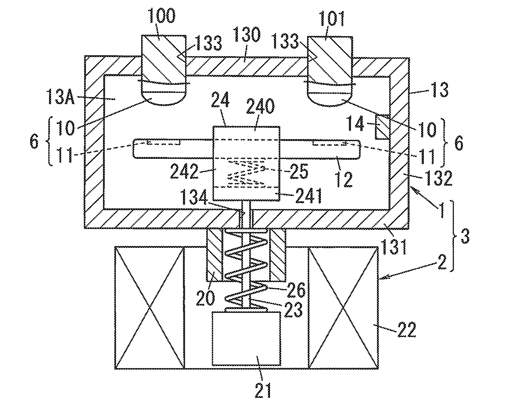
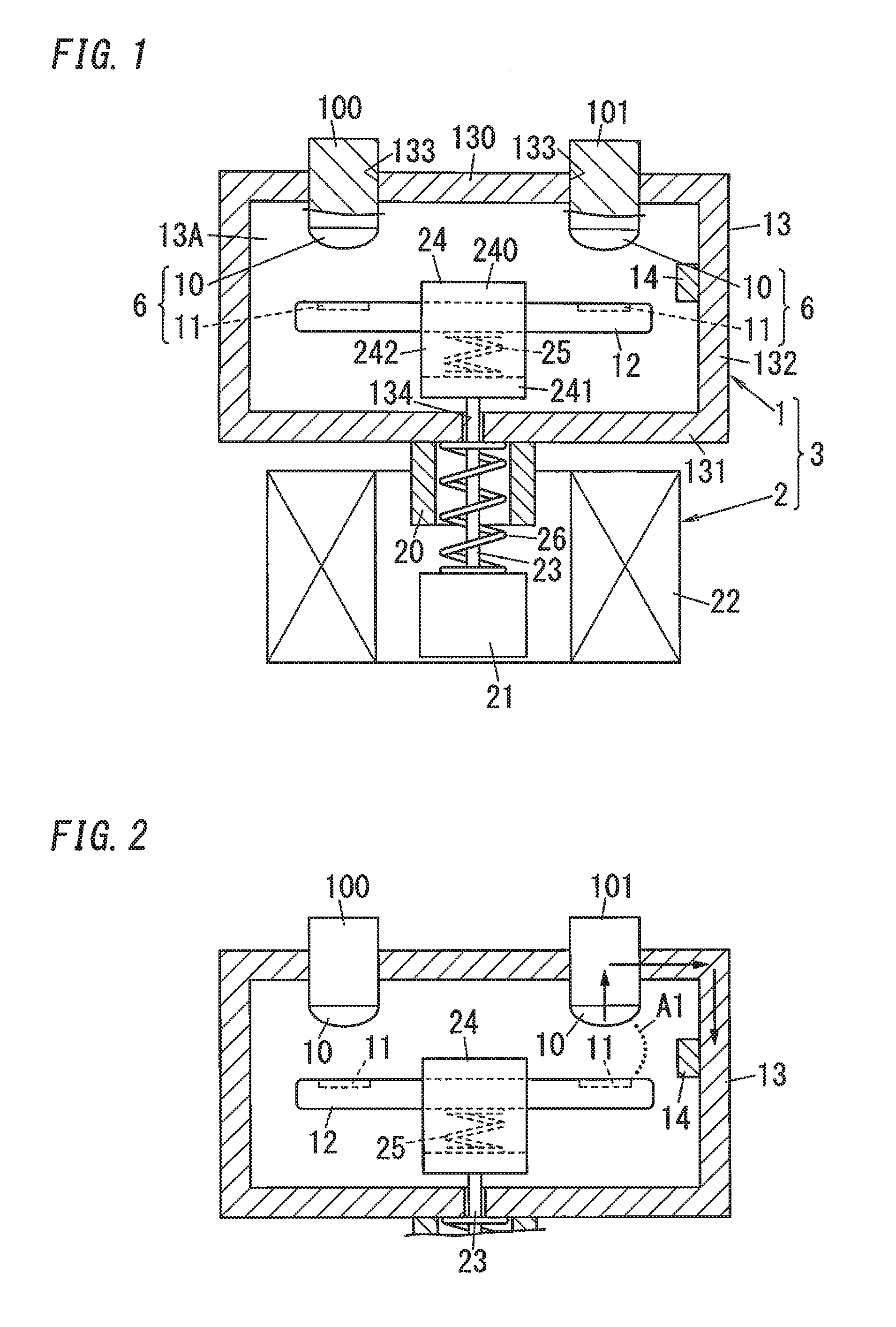
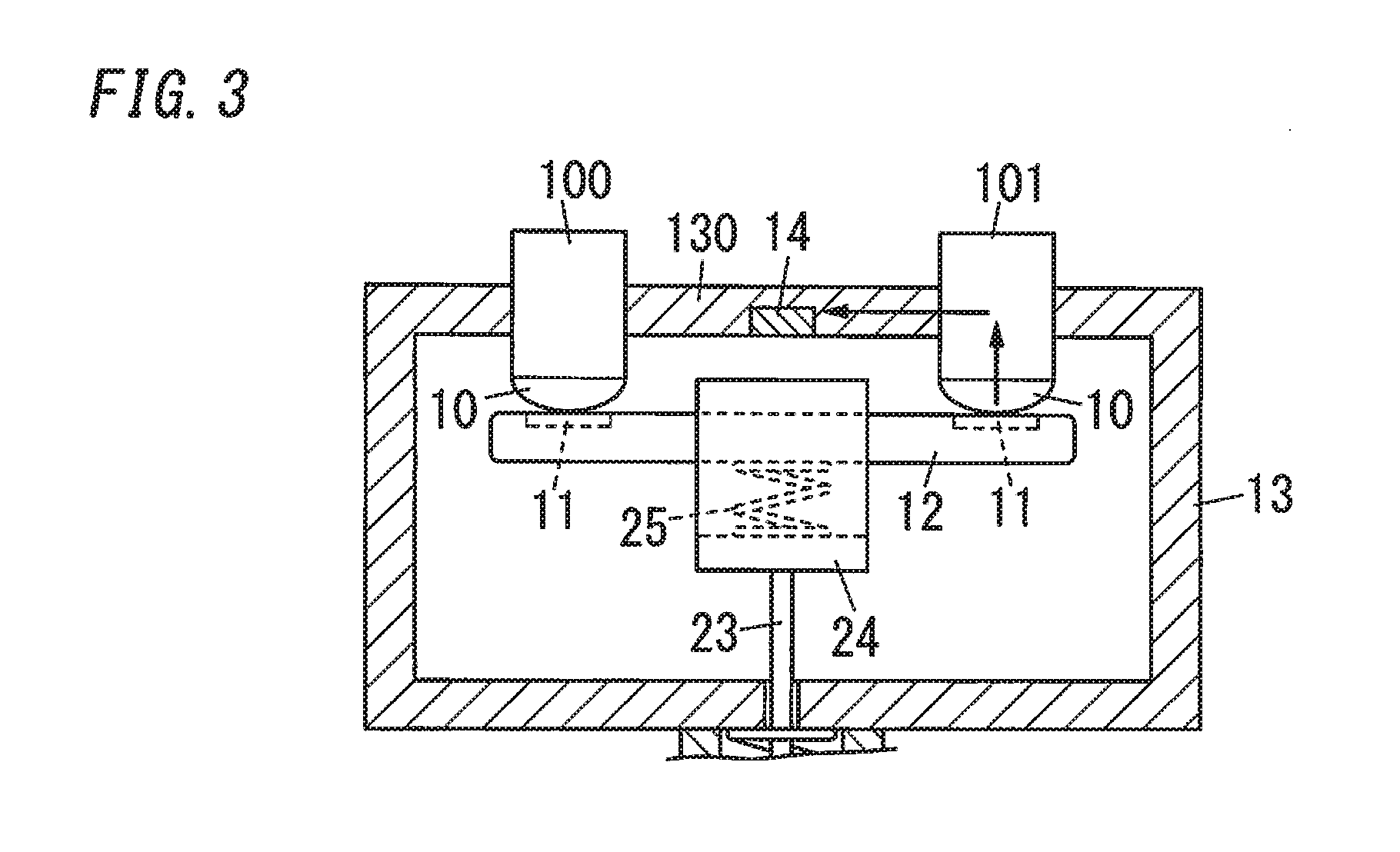
[0056]Hereinafter, a contact apparatus 1 of one embodiment of the present invention is described with reference to drawings. Note that, the contact apparatuses 1 described below are only examples of the present invention. The scope of the present invention is not limited to including only the below embodiment, and the embodiment may be modified in various ways in view of design or the like, provided that it is still inside the scope of the technical concept of the present invention. Further, in the following description, upward, downward, left and right directions shown in FIG. 1 correspond to upward, downward, left and right directions of the contact apparatus 1. In other words, in the following description, the upward and downward direction of the contact apparatus is defined by an axial direction of a shaft 23 described later. The upward direction of the contact apparatus is defined by a direction from the shaft 23 to a holder 24 described later, and the downward direction of the...
modification 1
(Modification 1)
[0093]FIG. 5A and FIG. 5B are schematic configuration diagrams of the contact apparatus 1 of Modification 1 of the present embodiment. The contact apparatus 1 of the present modification includes a magnetic field generator 15 for causing a magnetic field inside a space (the space 13A (shown in FIG. 1) inside the receptacle 13) including the fixed contact 10 and the movable contact 11, in addition to the components of the contact apparatus 1 of the embodiment. Other components of the present modification are the same as those of the embodiment, and the same components as the embodiment are designated by the same reference signs to avoid redundant explanations. Note that, FIG. 5B is a section of the contact apparatus 1 viewed from the upper side, and in the following explanation, an upward and downward direction of FIG. 5B corresponds to a forward and rearward direction of the modification.
[0094]The magnetic field generator 15 is constituted by a pair of magnets 150, w...
modification 2
(Modification 2)
[0098]FIG. 6A and FIG. 6B are schematic configuration diagrams of the contact apparatus 1 of Modification 2 of the present embodiment. The contact apparatus 1 of the present modification includes a gas flow generator 16 for causing a flow of gas inside a space (the space 13A inside the receptacle 13) including the fixed contact 10 and the movable contact 11, in addition to the components of the contact apparatus 1 of the embodiment. Other components of the present modification are the same as those of the embodiment, and the same components as the embodiment are designated by the same reference signs to avoid redundant explanations. Note that, FIG. 6B is a section of the contact apparatus 1 viewed from the upper side, and in the following explanation, an upward and downward direction of FIG. 6B corresponds to a forward and rearward direction of the modification.
[0099]The gas flow generator 16 is constituted by protrusions 160 protruding inward from centers in the lef...
PUM
 Abstract
Description
Claims
Application Information
 - R&D
- Intellectual Property
- Life Sciences
- Materials
- Tech Scout
- Unparalleled Data Quality
- Higher Quality Content
- 60% Fewer Hallucinations
Browse by: Latest US Patents, China's latest patents, Technical Efficacy Thesaurus, Application Domain, Technology Topic, Popular Technical Reports.
© 2025 PatSnap. All rights reserved.Legal|Privacy policy|Modern Slavery Act Transparency Statement|Sitemap|About US| Contact US: help@patsnap.com


