
Alternating valley switching for power converter

a power converter and alternating valley technology, applied in the field of power converters, can solve the problems of electric-magnetic interference, switching loss generation of switching devices, etc., and achieve the effect of avoiding electric magnetic interference and ensuring the stability of the power converter

Active Publication Date: 2016-08-18
SEMICON COMPONENTS IND LLC
View PDF0 Cites 28 Cited by
  • Summary
  • Abstract
  • Description
  • Claims
  • Application Information

AI Technical Summary

Benefits of technology

The patent text describes an alternating valley switching controller for a power converter. The controller includes a valley detection circuit and an alternating circuit that alternates a plurality of switching periods of a switching signal based on a blanking-window signal and a valley-detection signal. The blanking-window signal switches between a first voltage level and a second voltage level in the switching periods. The alternating circuit alternates between a first period and a second period in response to the first and second voltage levels. The control method involves alternating the switching periods and switching the power switch of the power converter accordingly. The technical effect of this invention is to improve the efficiency and stability of power converters by optimizing the timing of switching periods and reducing the peak-to-peak voltage levels of the current signal.

Problems solved by technology

However, the switching behavior of the switching device generates switching losses and electric-magnetic-interference (EMI).
However, when a valley is locked, the power converter has to operate at a lower operation frequency to keep the output power.
Thus, power converters with a valley locking operation may not operate at high frequencies.

Method used


Image

  • Alternating valley switching for power converter
  • Alternating valley switching for power converter
  • Alternating valley switching for power converter

Examples


Embodiment Construction

[0016]The following description is of the best-contemplated mode of carrying out the invention. This description is made for the purpose of illustrating the general principles of the invention and should not be taken in a limiting sense. The scope of the invention is best determined by reference to the appended claims.

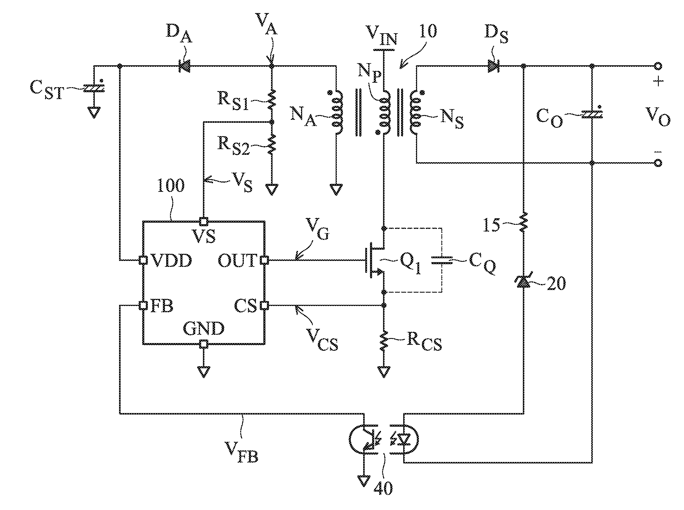
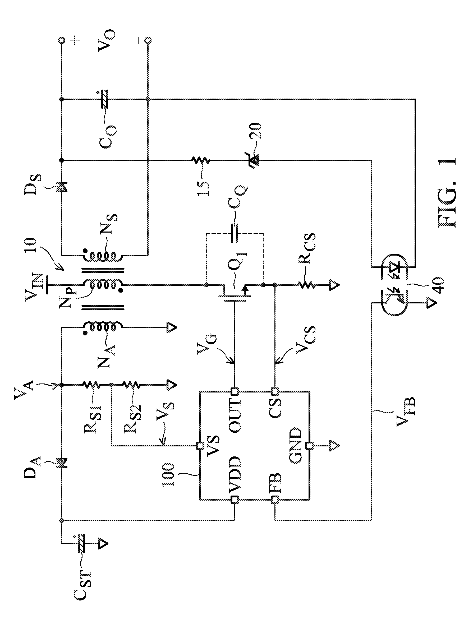
[0017]FIG. 1 shows an exemplary embodiment of a power converter. The power converter in the embodiment of FIG. 1 is a flyback power converter. Referring to FIG. 1, a transformer (magnetic device) 10 is coupled to an input voltage VIN of the power converter. The transformer 10 comprises a primary winding NP, a secondary winding NS and an auxiliary winding NA. A switching controller 100 includes a feedback terminal FB, a current-sense terminal CS, an input terminal VS, a power terminal VDD, and an output terminal OUT. A power switch Q1 is coupled with the primary winding NP. The switching controller 100 generates a switching signal VG through the output terminal OUT to c...


PUM


Abstract

An exemplary embodiment of an alternating valley switching controller is provided. The alternating valley switching controller includes a valley detection circuit and an alternating circuit. The valley detection circuit is coupled to an auxiliary winding of a transformer to generate a valley-detection signal. The alternating circuit alternates a plurality of switching periods of a switching signal according to a blanking-window signal and the valley-detection signal. The blanking-window signal switches between a first voltage level and a second voltage level in the plurality of switching periods. The plurality of switching periods includes at least two first periods and at least two second periods which occur alternately in response to the first voltage level and the second voltage of the blanking-window signal.

Description

CROSS REFERENCE TO RELATED APPLICATIONS[0001]This application claims the benefit of U.S. Provisional Application No. 62 / 117,066, filed on Feb. 17, 2015, the contents of which are incorporated herein by reference.BACKGROUND OF THE INVENTION[0002]1. Field of the Invention[0003]The invention relates to a power converter, and, more particularly, to a power converter with alternating valley switching.[0004]2. Description of the Related Art[0005]Power converters are used to convert an unregulated power source into a regulated voltage or current source. A power converter normally includes a transformer having a primary winding and a secondary winding to provide the isolation. The switching device connected to the primary winding controls the energy transfer from the primary winding to the secondary winding. A power converter operated at a high frequency allows for size and weight reduction. However, the switching behavior of the switching device generates switching losses and electric-magn...

Claims


Application Information

Patent Timeline
Patent Type & Authority Applications(United States)
IPC IPC(8): H02M3/335
CPCH02M3/33523H02M1/44H02M3/28H02M1/0054H02M1/08H02M1/0006H02M1/0009H02M1/0064Y02B70/10H02M1/0058
Inventor HSU, CHIEN-TSUNCHOI, HANG-SEOKHSIEH, CHIH-HSIEN
Owner SEMICON COMPONENTS IND LLC
Learn More