
Method and system for testing a mould shape quality of a user-customized ear mould

Active Publication Date: 2016-08-18
DYNAMIC EAR
View PDF7 Cites 5 Cited by
  • Summary
  • Abstract
  • Description
  • Claims
  • Application Information

AI Technical Summary

Benefits of technology

The patent describes a way to make ear mounds that fit better and sound better. We measure the sound waves in the ear to check the shape of the mound. This is done using a special test housing that can be connected to the mound. The test is done by listening to the sound waves instead of using pressure. The results are displayed on a screen and the mound can be changed if needed. Once the test is done, the ear pieces can be used for listening to music or making calls. The test is sensitive to the shape of the mound at low frequencies, and a higher frequency reference helps to measure the shape better.

Problems solved by technology

Unfortunately, for a universal ear piece, a trade-off is made between the requirement to adapt to different ear shapes by resilient expansion of the outer shape and a comfort level of the user who constantly feels the resilient housing of the ear piece trying to expand inside his ear canal.
However the pumping makes a lot of noise in the ear.
Secondly, either over or under pressure gives an unpleasant feeling, since the tympanic membrane is stretched.
Thirdly overpressure tends to push out the ear mould out of the more or less wedge shaped ear canal, which could lead to the unfair judgement that the mould shape does not fit.
On the other hand under pressure could lead to sucking in the earpiece, which could lead to the unfair judgement that the mould shape does fit.
Finally, the equipment for testing the mould shape as described above is expensive.
These and other drawbacks leads to the situation that the mould shape quality is often not tested, whereas this is very important.
It is recognized that a customized ear mould that is not correctly shaped to fit the ear canal can lead to diminished user comfort and deteriorated quality of the sound.

Method used


Image

  • Method and system for testing a mould shape quality of a user-customized ear mould
  • Method and system for testing a mould shape quality of a user-customized ear mould
  • Method and system for testing a mould shape quality of a user-customized ear mould

Examples


first embodiment

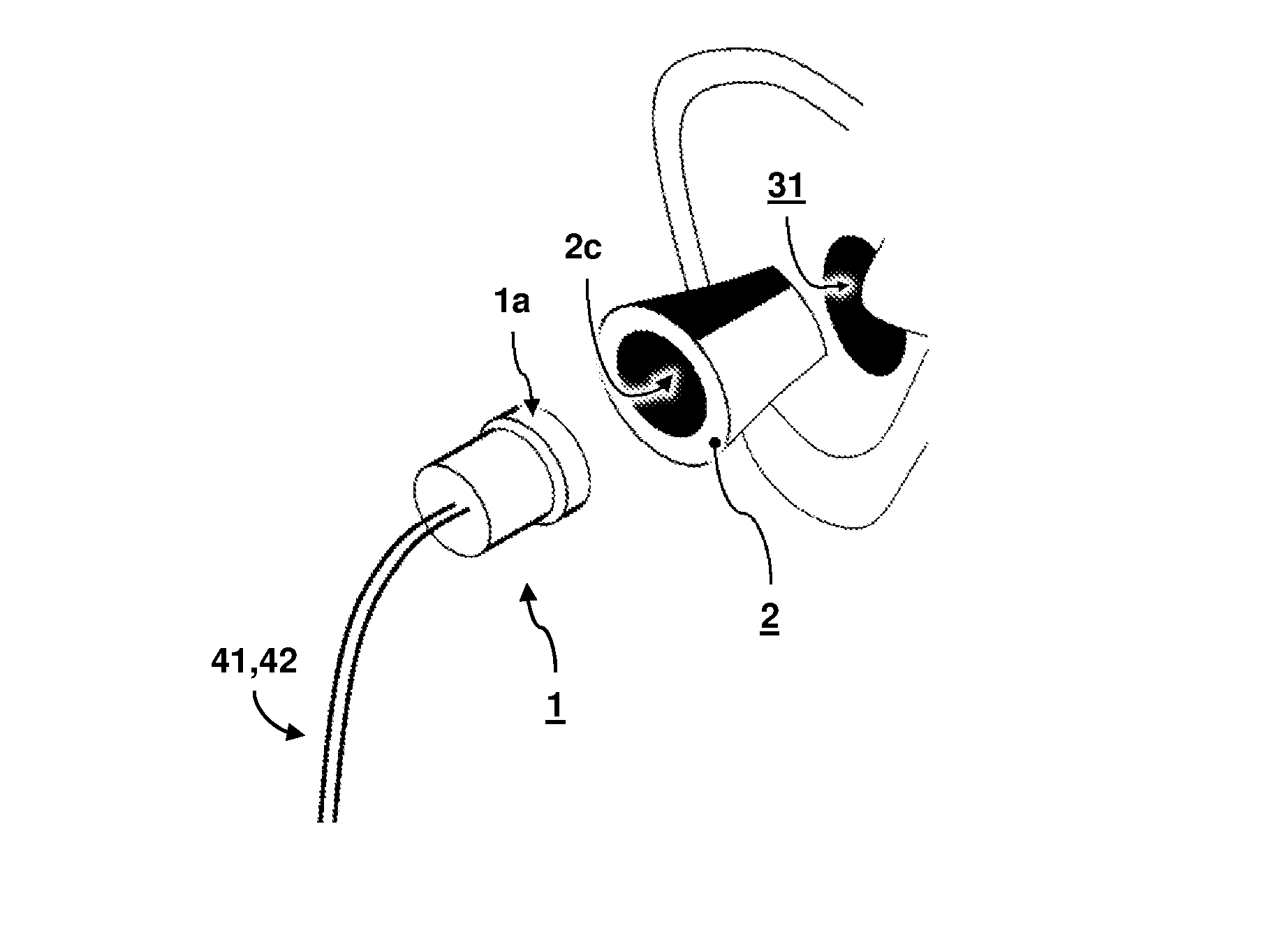
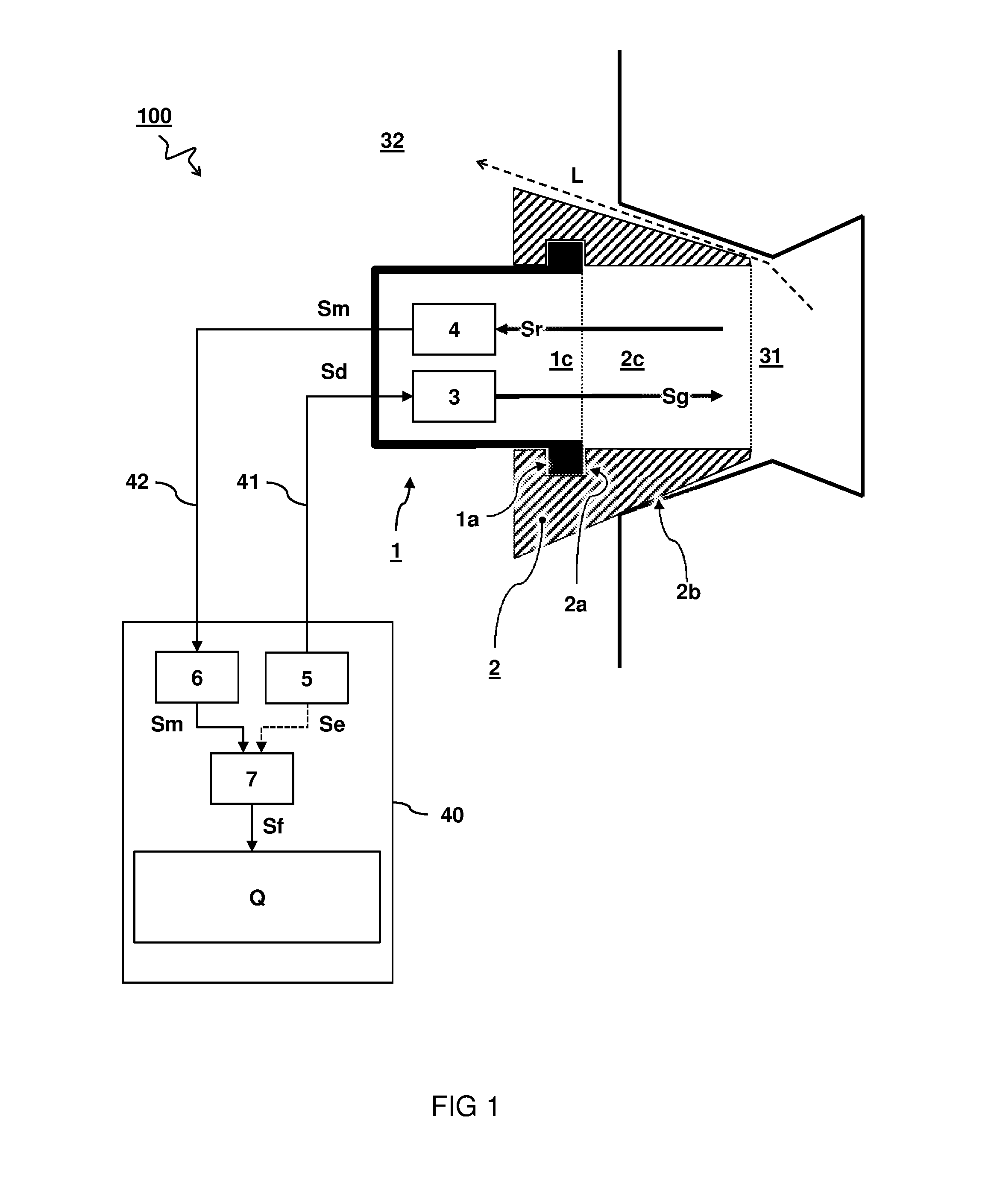
[0043]FIG. 5A shows a test housing 1 and an ear mould 2. The test housing 1 comprises wiring 41 connected to acoustic generator 3 and wiring 42 connected to microphone 4. The test housing 1 can be connected to the ear mould 2 by means of the outer contour 1a fitting into the clamping structure 2a. The ear mould 2 comprises an outer contour 2b that is custom designed to acoustically fit into an ear canal (not shown here). When connected, the microphone 4 allows to measure sound played with the acoustic generator 3, also referred to as a receiver or loudspeaker. In particular, in the embodiment shown, the microphone 4 is capable of measuring the sound level in the sound path between the loudspeaker and the eardrum, at least when the test housing 1 is connected to the ear mould 2.

second embodiment

[0044]FIG. 5B shows a test housing 1 comprising a moving coil driver as the acoustic generator 3 with a microphone 4 enclosed in the back volume. The acoustic generator 3 comprises a cone 3a and magnet 3b. The acoustic generator 3 is connected by wiring 41 and the microphone 4 is connected by wiring 42. In the embodiment, the microphone 4 is integrated in or situated just behind the receiver unit, i.e. acoustic generator 3, measuring the sound in the loudspeaker's inner volume that is acoustically connected to the chamber of the test housing behind the moving coil unit.

third embodiment

[0045]FIG. 5C shows a test housing 1 wherein the acoustic generator 3 comprises a balanced armature receiver. In the embodiment, the microphone 4 is situated in the chamber of the test housing behind the receiver unit 3 acoustically connected to the receiver unit through its vent 3v measuring the sound in the chamber behind the loudspeaker unit.

[0046]In one embodiment, the microphone 4 is located opposite the acoustic generator 3 with respect to the open end 1c of the housing 1. In other words, the acoustic generator 3 is arranged between the microphone 4 and the open end 1c. In this way, the wiring 42 connecting to the microphone 4 does not have to pass the acoustic generator 3. An advantage of having the microphone 4 located opposite the acoustic generator 3 with respect to the open end 1c, e.g. as sketched in FIGS. 5B and 5C, is that the diameter of the test housing 1 can be smaller, which makes it easier to connect the test housing to customized ear moulds of users with a relati...


PUM


Abstract

The present disclosure concerns a method for determining a mould shape quality (Q) of an ear mould (2) customized to an ear canal (31) of a user by means of a mould testing system (100). The mould testing system (100) comprises an acoustic generator (3) and a microphone (4) arranged in a test housing (1) with an open end (1c) that is connectable to an inner passage (2c) of the custom ear mould (2). The method comprises inserting the ear mould (2) into the ear canal (31); connecting the test housing (1) to the ear mould (2); generating an acoustic signal (Sg) into the ear canal (31) via the inner passage (2c); measuring the acoustic signal (Sr) from the ear canal (31); comparing the measured signal (Sm) with a reference signal (Se); and providing a feedback signal (Sf) based on the said comparison. The feedback signal (Sf) is a measure for the mould shape quality (Q) of the custom ear mould (2).

Description

TECHNICAL FIELD AND BACKGROUND[0001]The present disclosure concerns a method for determining a mould shape quality of a user-customized ear mould for an ear piece by means of a mould testing system; the disclosure further concerns a mould testing system for determining a mould shape quality of a user-customized ear mould for an ear piece.[0002]An ear piece is worn in the ear of a user to provide a desired functionality, e.g. hearing aid. The ear piece typically comprises an outer shape or contour designed to fit at least partly into an ear canal. By its outer shape, the ear piece can e.g. be retained in the ear without further support. For some ear pieces it can be desirable that the ear piece acoustically fits into the ear canal, e.g. to block outside noise and / or prevent deterioration of sound generated by the ear piece.[0003]One class of ear pieces has a universal shape that is designed to more or less adapt their shape to the ear of an average individual. Unfortunately, for a un...

Claims


Application Information

Patent Timeline
IPC IPC(8): H04R25/00
CPCH04R25/30H04R2460/15H04R2225/025
Inventor VAN 'T HOF, PIETER GERARDWILMINK, ENGBERT
Owner DYNAMIC EAR
Learn More