
Speaker

Active Publication Date: 2012-05-24
ALPINE ELECTRONICS INC
View PDF5 Cites 2 Cited by
  • Summary
  • Abstract
  • Description
  • Claims
  • Application Information

AI Technical Summary

Benefits of technology

[0011]To address the above issues, the present invention provides a speaker with a ring-shaped vibrating member having a structure in which sound pressure decrease and sound quality deterioration are less likely to occur when listening at diagonal front against a center line.
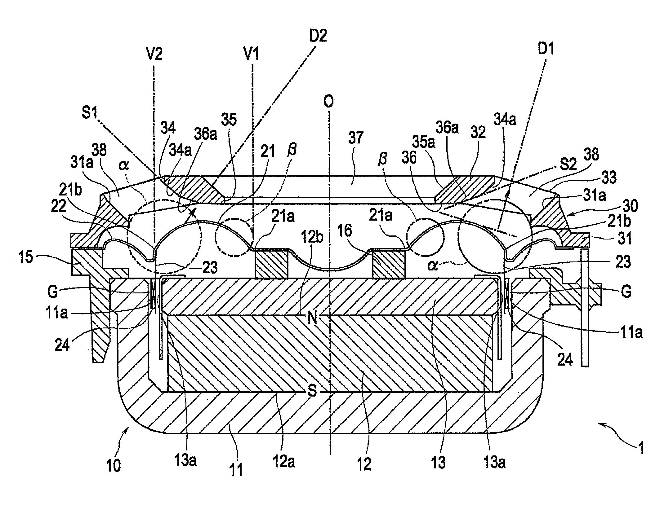
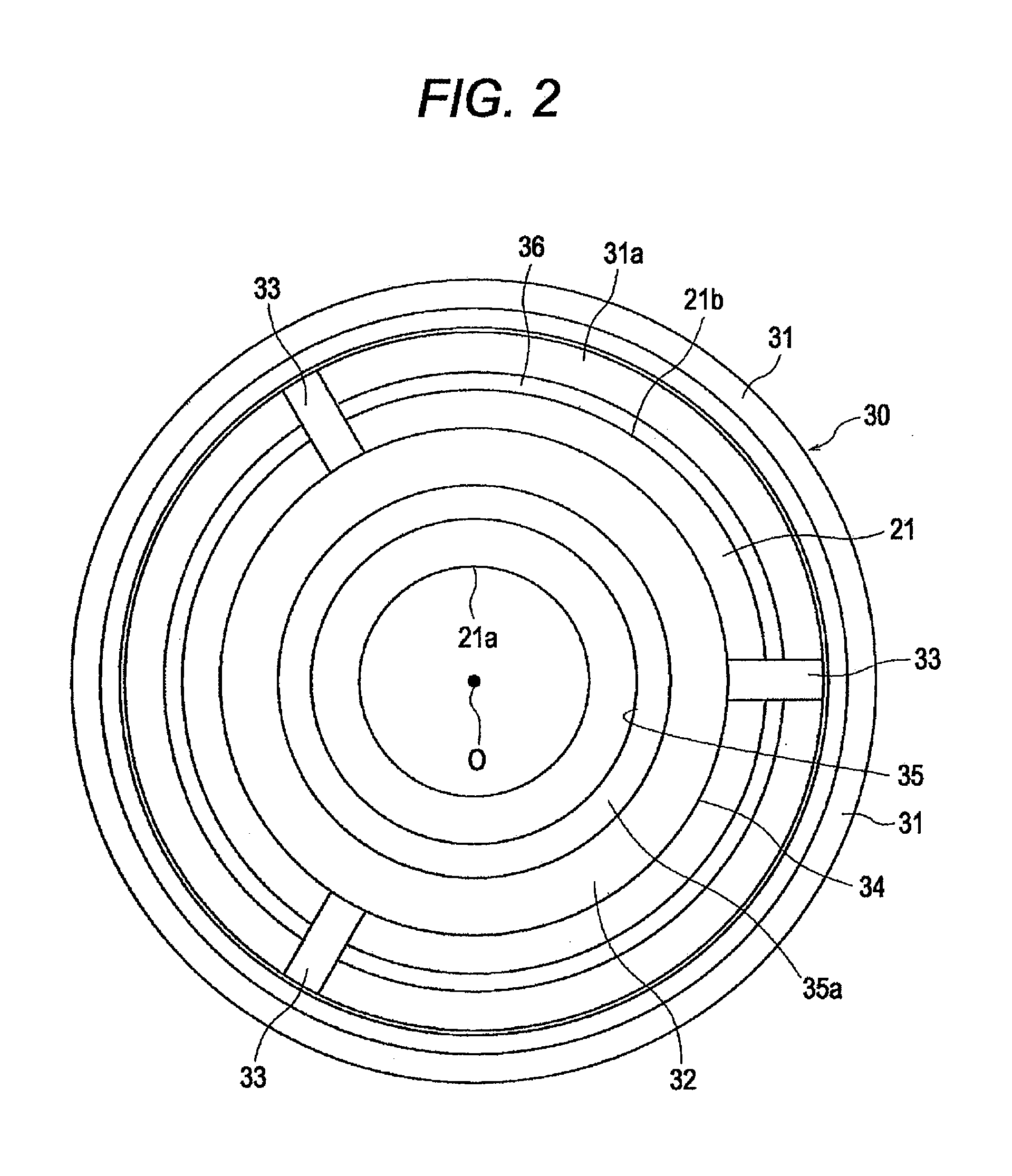
[0019]In the speaker of the present invention, the ring-shaped control member is faced to the front of the ring-shaped vibrating member. When sound is listened from diagonal front being angled against the center line, a sound wave generated from a sound-generating portion at a position of the inclined side sandwiching the center line is more likely to be transmitted to a person through the pass space located outside the external peripheral end portion of the control member. However, propagation of a sound wave generated from a sound-generating portion at an opposite position to the inclined side is more likely to be suppressed. Accordingly, interference between sound waves from the bilateral sound-generating portions can be suppressed and sound pressure decrease and sound quality deterioration can be suppressed.
[0020]In contrast, when sound is listened at the front on the center line of the speaker, sound waves generated from the ring-shaped vibrating member are transmitted frontward through the pass space which is surrounded by the internal peripheral end portion of the control member, so that the sound waves are more likely to be transmitted to a person without causing phase difference.
[0022]With the above structure, the sound waves generated from the ring-shaped vibrating member are more likely to be guided to diagonally frontward as being guided by the inclined side face. Accordingly, when listening from the front being diagonal against the center line, decrease of the sound pressure level is easy to be suppressed.
[0024]In the above structure, resonance at the opposite portion between the vibrating member and the control member is less likely to occur, so that sound quality deterioration caused by the resonance is easy to be prevented.
[0026]A speaker of the present invention utilizes a ring-shaped vibrating member and is likely to prevent occurrence of sound pressure decrease and sound quality deterioration when listening sound from diagonal front.

Problems solved by technology

The ring-shaped vibrating member is unlikely to cause divisional resonance compared to a circular dome-shaped vibrating member and to cause sound distortion.
Since treble sound waves have short wavelength and high directivity, sound pressure is more likely to be decreased and sound quality is more likely to be deteriorated when listening at diagonal front owing to interference between sound waves from the sound-generating portions located at both sides as sandwiching the center line.

Method used


Image

  • Speaker
  • Speaker
  • Speaker

Examples


examples

[0060]FIG. 4 is a graph of comparison between sound pressure levels of the speaker of the embodiment of the present invention and a speaker of the related art.

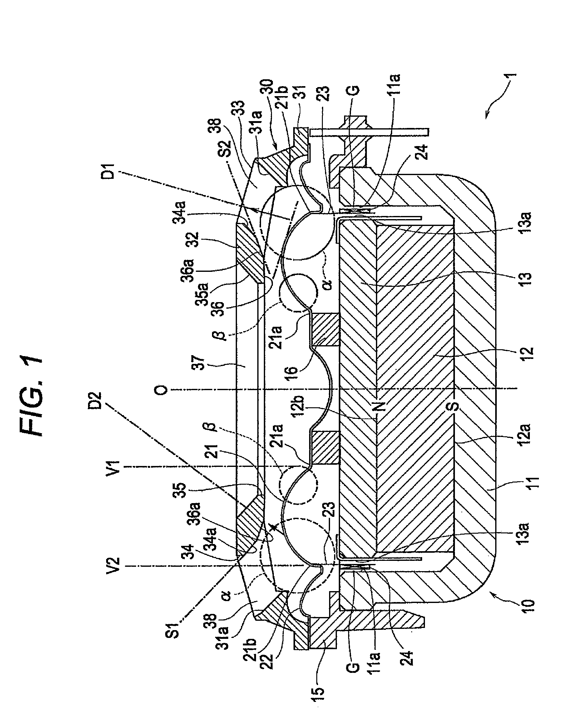
[0061]The speaker 1 of the embodiment has the structure as illustrated in FIG. 1. The external peripheral edge 21b of the vibrating member 21 is 25 mm in diameter. A speaker of the comparison example is the same as the speaker of the embodiment while the equalizer 30 is detached.

[0062]A high frequency signal of 1 watt was applied to the voice coil 24. The pressure levels were measured at a position being apart from the vibrating member 21 by 1 meter at diagonal front angled by 20 degrees from the center line as varying the frequency.

[0063]In FIG. 4, the horizontal axis denotes frequency and the vertical axis denotes a sound pressure level. A result of the embodiment is indicated by (a) and a result of the comparison example is indicated by (b). According to FIG. 4, it is perceptible that decrease of the sound level of the embo...


PUM


Abstract

A speaker includes a ring-shaped vibrating member fixed to an internal support body at an internal peripheral edge, and a bobbin attached to an external peripheral edge thereof. A voice coil is attached to the bobbin and is located in a magnetic gap. A ring-shaped control member faces a front portion of the vibrating member, and a sound pass space is formed at an external peripheral side of the control member and at an internal peripheral side thereof. When listening to the speaker from a diagonal location, treble sound waves generated from the left side area are perturbed by the control member so as to prevent interference from sound waves generated from bilaterally separated areas, which prevents a decrease of treble sound pressure levels.

Description

PRIORITY CLAIM[0001]This application claims the benefit of Japanese Patent Application No. 2010-257775, filed on Nov. 18, 2010, and which is incorporated by reference herein in its entirety.BACKGROUND[0002]1. Field of the Invention[0003]The present invention relates to a speaker which includes a ring-shaped vibrating member, and in particular, relates to a speaker which can prevent decrease of sound pressure and deterioration of sound quality when listening at diagonal front.[0004]2. Description of the Related Art[0005]Speakers respectively utilizing a ring-shaped vibrating member have been disclosed in Japanese Patent Application Laid-open 2006-100879, Japanese Patent Application Laid-open 2009-171475, and U.S. Pat. No. 6,320,972.[0006]The ring-shaped vibrating member is unlikely to cause divisional resonance compared to a circular dome-shaped vibrating member and to cause sound distortion. Accordingly, such a vibrating member is often used for a tweeter which generates sound mainl...

Claims


Application Information

Patent Timeline
IPC IPC(8): H04R1/00
CPCH04R7/12H04R1/323H04R7/18
Inventor SHIMAMURA, NAOKI
Owner ALPINE ELECTRONICS INC
Learn More