Snow removal machine

a technology of snow removal machine and adjusting machine, which is applied in the direction of snow cleaning, way cleaning, construction, etc., can solve the problems of affecting the safety of workers,

Active Publication Date: 2016-08-25
HONDA MOTOR CO LTD
View PDF2 Cites 16 Cited by
  • Summary
  • Abstract
  • Description
  • Claims
  • Application Information

AI Technical Summary

Benefits of technology

[0006]In view of the foregoing prior art problems, it is an object of the present invention to provide an improved snow removal technique which can au

Problems solved by technology

However, if the snow throwing place is small, or if the thrown snow is to be gathered in one place, the human operator has to frequently adjust the chute and the chute guide, and such frequent adjusting operation is very bothersome.
Besides, because the human operator has to frequently adjust the snow

Method used


Image

  • Snow removal machine
  • Snow removal machine
  • Snow removal machine

Examples


first embodiment

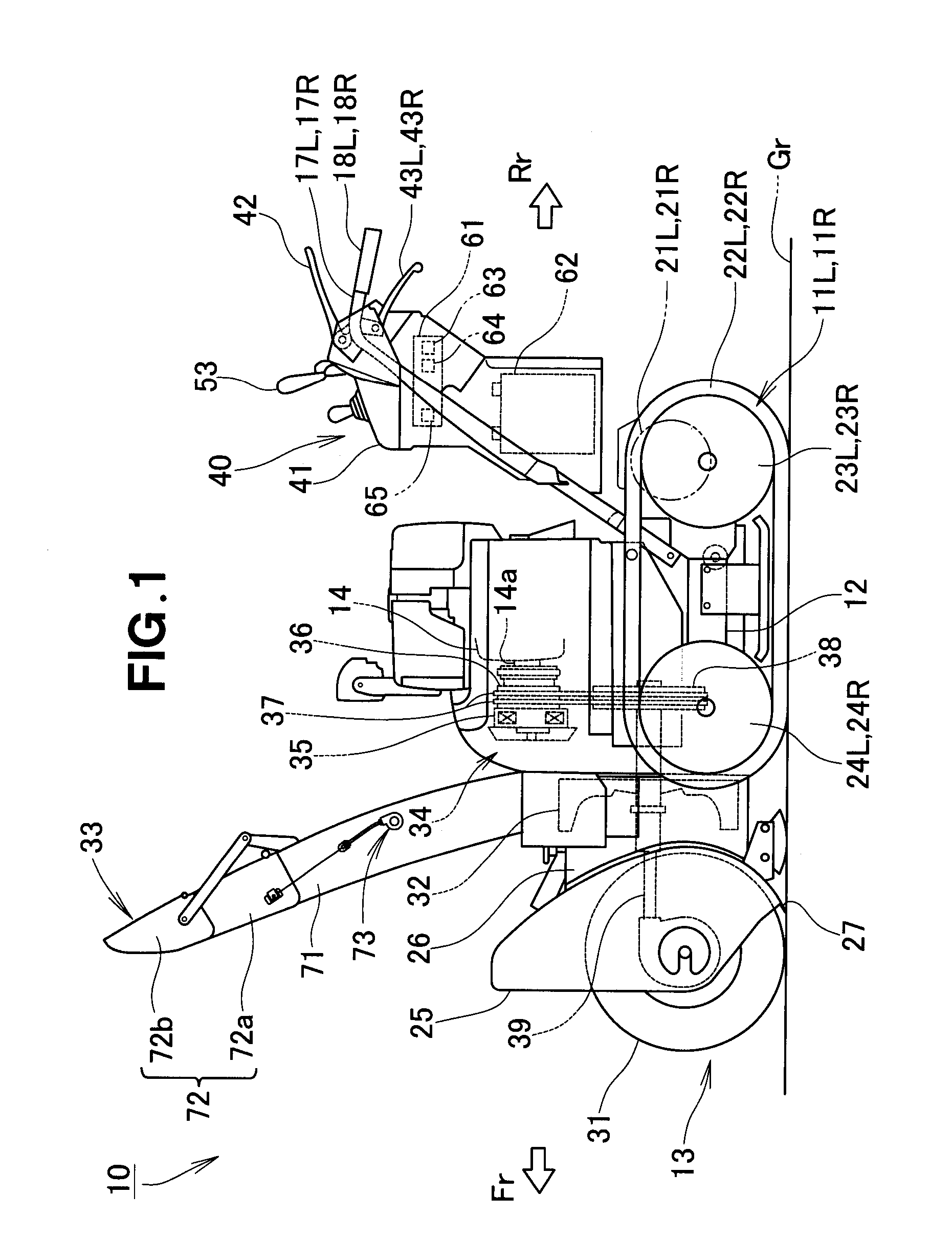
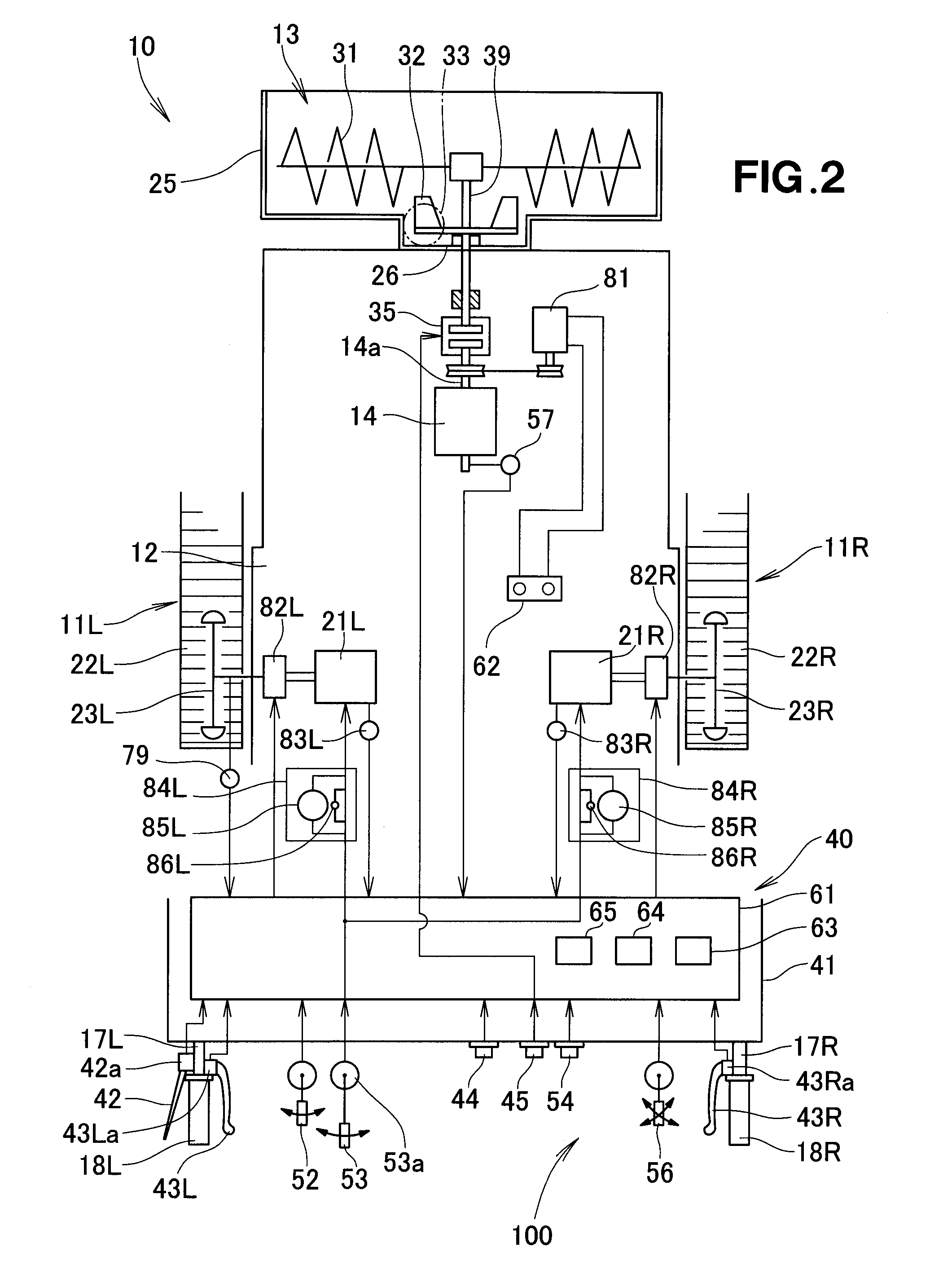
[0038]A first embodiment of the snow removal machine 10 of the present invention, as shown in FIGS. 1 and 2, is a self-propelled, auger type snow removal machine (also called a rotary snow removal machine) 10 which includes: left and right travel units 11L and 11R; a travel unit frame 12 having left and right travel units 11L and 11R mounted thereon; a snow removal work section 13 and an engine 14 mounted to the travel unit frame 12; and an engine 14.

[0039]More specifically, the travel unit frame 12 constitutes a machine body of the entire snow removal machine 10. The engine 14 is a drive source for driving the snow removal work section 13. Left and right operating handles 17L and 17R are mounted to rear portions of the travel unit frame 12 and extend obliquely rearwardly and upwardly from the travel unit frame 12. Left and right grips 18L and 18R are mounted to the distal ends of the left and right operating handles 17L and 17R, respectively.

[0040]The travel unit frame 12 also has ...

second embodiment

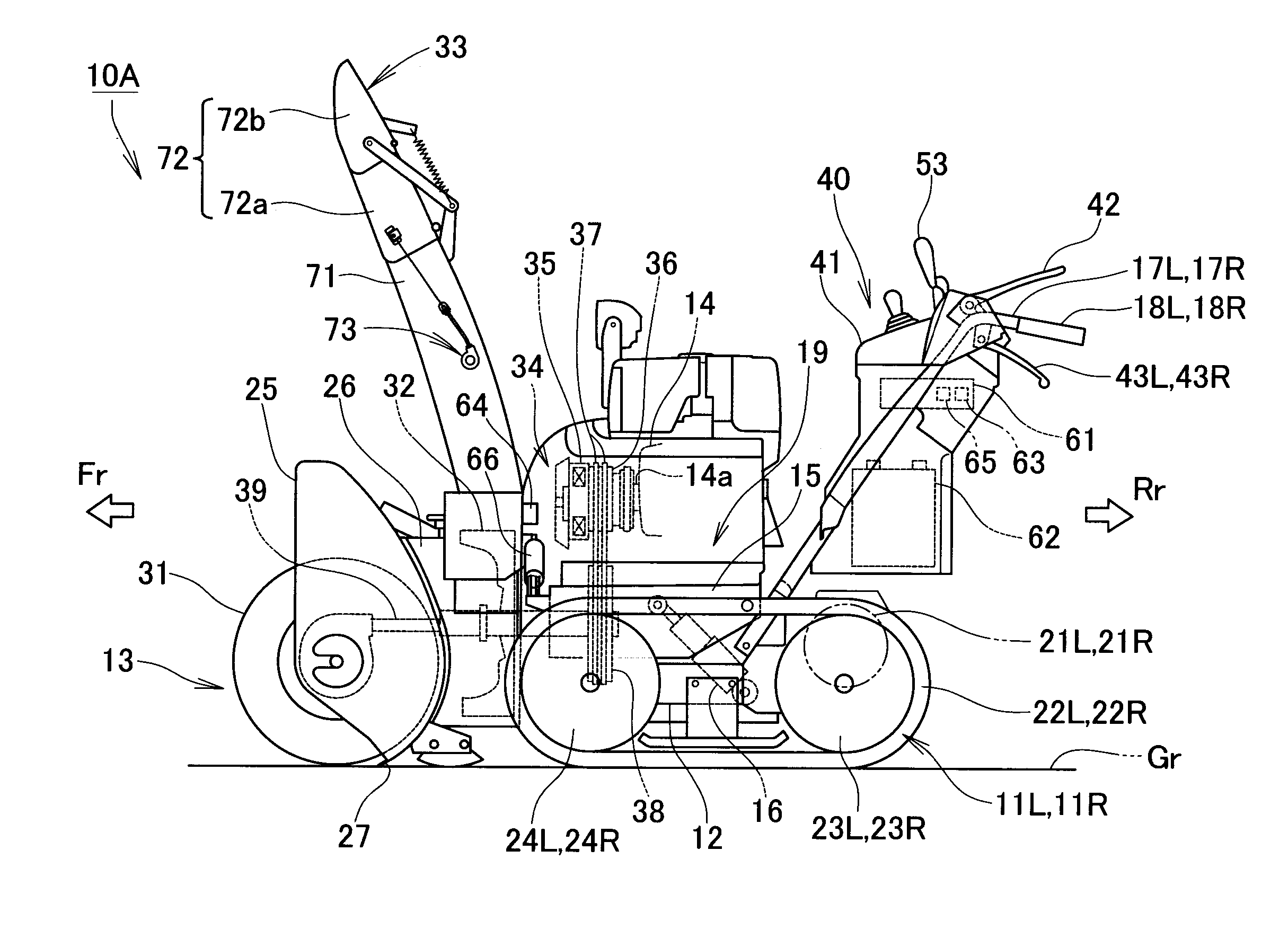
[0134]Next, a description will be given about a second embodiment of the snow removal machine of the present invention with reference to FIGS. 13 to 17, of which FIG. 13 corresponds to FIG. 1, FIG. 14 corresponds to FIG. 2 and FIG. 15 corresponds to FIG. 4.

[0135]The second embodiment of the snow removal machine 10A of the present invention shown in FIG. 13 is different from the first embodiment of the snow removal machine 10 of the present invention shown in FIG. 1 in that the snow removal work section 13 in the second embodiment is movably mounted to the travel unit frame 12 and in that the snow removal machine inclination angle sensor 64 in the second embodiment is located on the auger housing 25 or the blower case 26. The other structural features of the second embodiment of the snow removal machine 10A are the same as in the first embodiment of the snow removal machine 10 shown in FIGS. 1 to 12 and thus will not be described to avoid unnecessary duplication.

[0136]More specifical...

third embodiment

[0148]Next, a description will be given about a third embodiment of the snow removal machine of the present invention with reference to FIGS. 18 to 20, of which FIG. 18 corresponds to FIG. 14.

[0149]The third embodiment of the snow removal machine 10B of the present invention shown in FIG. 18 is different from the above-described second embodiment of the snow removal machine 10A of the present invention shown in FIG. 13 in that the snow removal machine inclination angle sensor 64 is built in or provided in the control section 61 as in the first embodiment or mounted on the travel unit frame 12, and in that a height position sensor 87 and a rolling position sensor 88 are added. The other structural features of the third embodiment of the snow removal machine 10B are based on the construction of the first embodiment and generally the same as some of the structural features of the second embodiment and thus will not be described here to avoid unnecessary duplication.

[0150]Further, as sh...


PUM


Abstract

Disclosed is a snow removal machine capable of adjusting a snow throwing direction of a snow throwing section by means of a snow throwing drive section, which comprises: a snow throwing direction sensor for detecting a snow throwing direction of the snow throwing section; a snow removal machine inclination angle sensor for detecting an inclination angle of the snow removal machine or the snow throwing section relative to a horizontal surface; and a control section that controls the snow throwing drive section to adjust the snow throwing direction of the snow throwing section based on respective detection values of the snow throwing direction detected by the snow throwing direction sensor and the inclination angle detected by the snow removal machine inclination angle sensor.

Description

FIELD OF THE INVENTION[0001]The present invention relates to snow removal machines where a snow throwing direction of a snow throwing section is adjustable via a snow-throwing drive section.BACKGROUND OF THE INVENTION[0002]Among the conventionally-known snow removal machines are snow removal machines which include a snow discharge member (snow blade) provided on a front section of a machine body, and auger type snow removal machines which throw accumulated snow by means of a snow throwing section. The auger type snow removal machines gather accumulated snow by means of an auger provided on a front section while traveling forward and can throw away the gathered snow by a blower through a chute. A chute guide, which is a vertically pivotable member for adjusting a snow throwing angle in a vertical or up-down direction, is provided on a distal end portion of the chute. The chute and the chute guide are components of the snow throwing section.[0003]In ordinary auger type snow removal ma...

Claims


Application Information

Patent Timeline
IPC IPC(8): E01H5/04
CPCE01H5/045
Inventor YUKI, TORUFUKANO, JUNNAKAYAMA, SHINSAKUHIROSE, YOSHIHISA
Owner HONDA MOTOR CO LTD
Why Eureka
Try Eureka