Locating a tag in an area

a technology for locating tags and areas, applied in direction finders, instruments, measurement devices, etc., can solve the problems of low accuracy, low accuracy, and inability to provide complete, up to date and accurate knowledge of the whereabouts of nodes, etc., to achieve accurate time difference calculations, lower hardware costs, and accurate time difference calculations

Inactive Publication Date: 2016-09-08
BEESTAR BV
View PDF4 Cites 9 Cited by
  • Summary
  • Abstract
  • Description
  • Claims
  • Application Information

AI Technical Summary

Benefits of technology

[0014]The embodiments of claims 4 and 15 advantageously enable accurate time difference calculations on high resolution pulses.
[0015]The embodiments of claims 5 and 16 advantageously enable accurate time difference calculations on high frequency pulses with lower cost hardware. By stretching the high resolution signal through subsampling the time difference calculation can be performed at a lower resolution.
[0016]The embodiments of claims 6 and 17 advantageously enable an alternative accurate time difference calculations on high frequency pulses with lower cost hardware. By stretching the signal through subsampling the time difference calculation can be performed at a lower resolution. Furthermore, by performing the cross-correlation in the frequency domain high performance multipliers are not required.
[0017]The embodiments of claims 7 and 18 advantageously increase the accuracy of the time difference of arrival calculation.
[0018]The embodiments of claims 8 and 19 advantageously enable the tag to be small sized, e.g. coin sized. Furthermore, the tag can be very flat, enabling it to be e.g. comfortably integrated in clothing. The leaky lens antenna has a frequency independent phase center and is particularly suitable for generating UWB signals. It has been found by surprise that the properties of the leaky lens antenna can be used for accurately locating a tag utilizing the leaky lens antenna for transmitting UWB pulses. These UWB pulses have sharp edges. It has advantageously been found that these characteristics can be used as defined in the claims. As a result the signal at the receiving antennas has a high quality compared to prior art signals used for localizing tags. Because of the high frequencies used in UWB, the receiver of the present invention is typically adapted for fast processing of the signal.

Problems solved by technology

Solutions based on Near Field ID Cards and barcodes e.g. can provide snapshots of discrete moments, but fail in providing a complete, up to date and accurate knowledge of the whereabouts of nodes.
Systems based on e.g. WIFI, Bluetooth and Zigbee provide positioning possibilities, but behave poorly in the neighborhood of walls, people and water sources.
This is due to the fact that these technologies operate in a bandwidth that has been conceived for data transmission purposes and they are improperly employed in poorly designed short range tracking solution.
Other known GPS or GPRS / 3G solutions are expensive and provide best localization outdoors only.
Without constant phase centers, the UWB signal characteristic of spanning across a large number of frequencies, would introduce intolerable phase distortion which would vary the aforementioned distance, making the determination of the angular offset less accurate or even not possible.
Also, it is not disclosed how the high frequency characteristics of UWB signals can be used and processed.

Method used


Image

  • Locating a tag in an area
  • Locating a tag in an area
  • Locating a tag in an area

Examples


Embodiment Construction

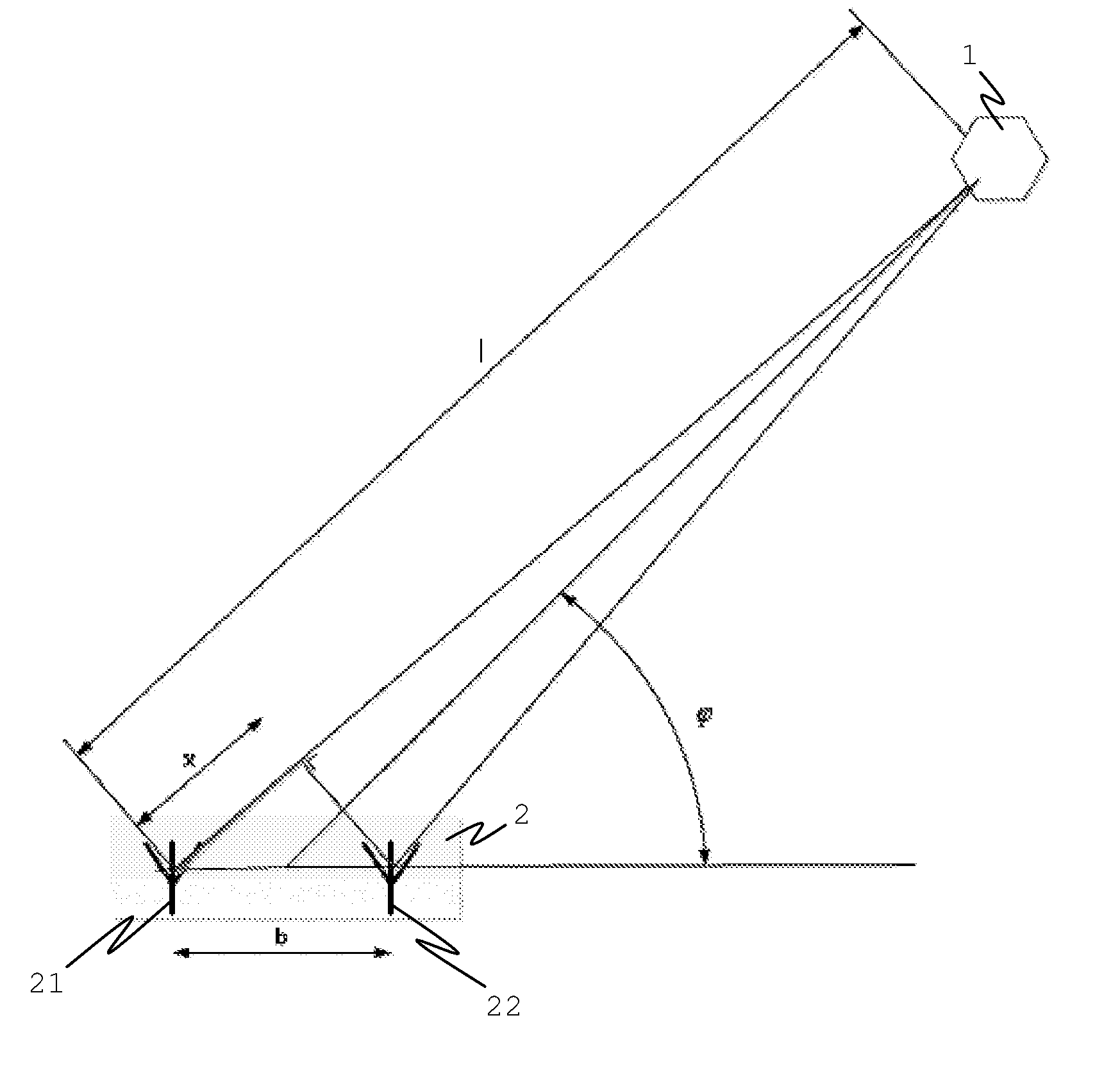
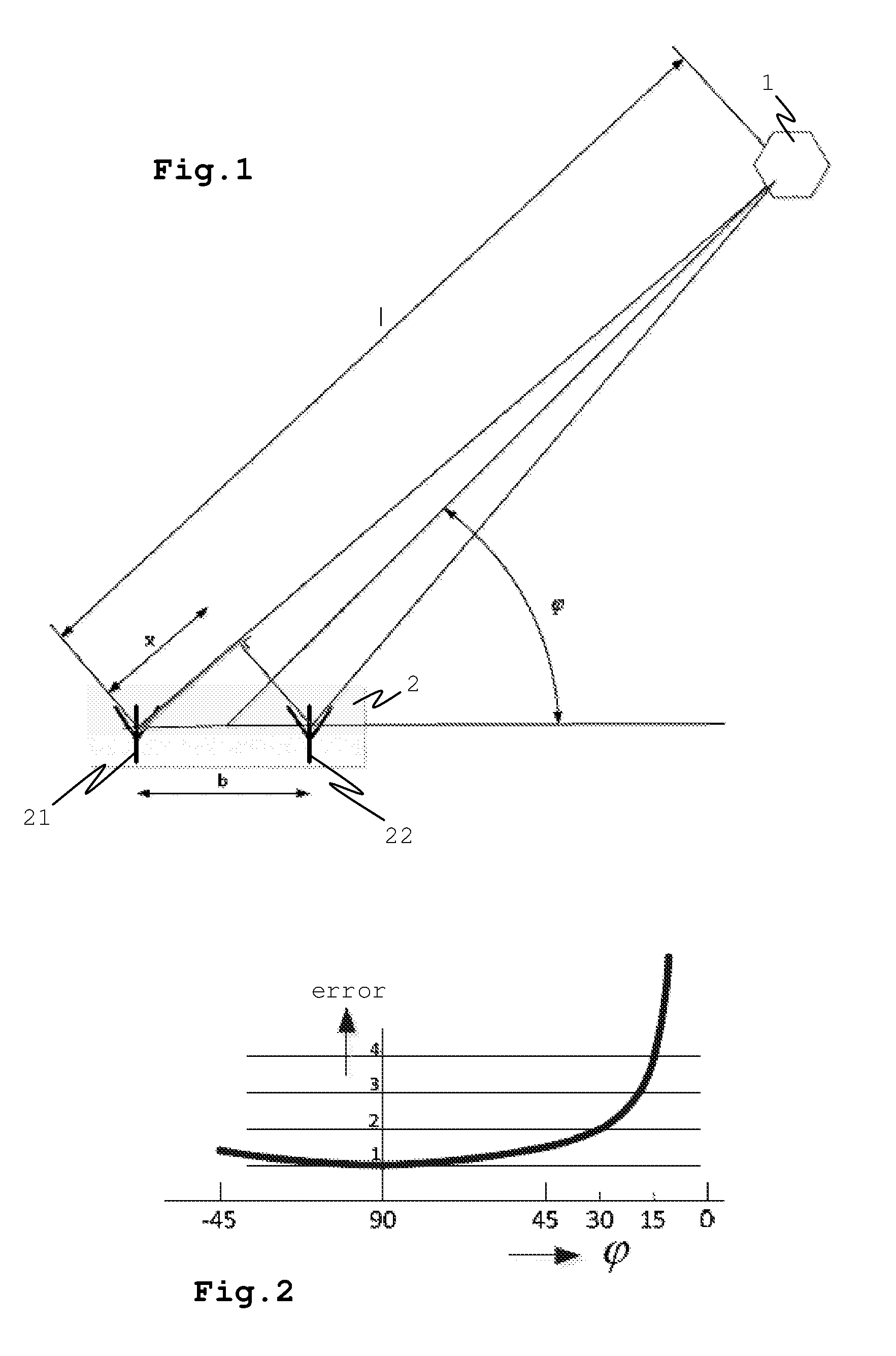
[0036]The following is a description of certain embodiments of the invention, given by way of example only and with reference to the drawings. FIG. 1 shows a basic set up for an estimation of an angle of arrival of a signal originating from a tag 1 at two antennas 21,22 of a receiver 2. The tag 1 transmits an electromagnetic wave or pulse. The signal path 1 from the tag to the left antenna 21 is longer than the path to the right antenna 22, as shown in FIG. 1. This path difference may be measured as a time difference of arrival of the signal at the left antenna 21 and the right antenna 22. The time difference may be converted to a distance difference x as shown in FIG. 1. Under the condition that the distance from the tag 1 to the receiver 2 is bigger than the distance b between the two receive antennas 21,22, the following relation between the angle φ and the distance x holds:

φ=arcos(x / b)  [equation 1]

[0037]Inaccuracies in x will result in an error in the angle φ. The following rel...


PUM


Abstract

A method and system for locating a tag. The system has a first receiver configured to receive a signal from a tag. The first receiver has at least two antennas each configured to receive the signal. The system is configured to calculate a first angle of arrival of the signal at the first receiver based on a distance between a first set of two antennas of the first receiver and a time difference of arrival of the signal at the two antennas of the first set. The tag has a tag antenna that is configured to transmit signals having a wide bandwidth and has a frequency independent phase center and wherein the signal is an ultra wideband signal having one or more pulses.

Description

CROSS REFERENCE TO RELATED APPLICATIONS[0001]This application is a continuation of PCT application number PCT / EP2013 / 065642 filed on 24 Jul. 2013, the disclosure of which is hereby incorporated by reference in its entirety.BACKGROUND OF THE INVENTION[0002]1. Field of the Invention[0003]The invention relates generally to positioning and / or tracking of tags in an area, and more particularly, to a system for locating a tag, a first receiver for use in a system for locating a tag and a method for locating a tag.[0004]2. Description of the Related Art[0005]Systems for positioning and tracking of nodes in an area are known. Solutions based on Near Field ID Cards and barcodes e.g. can provide snapshots of discrete moments, but fail in providing a complete, up to date and accurate knowledge of the whereabouts of nodes. Systems based on e.g. WIFI, Bluetooth and Zigbee provide positioning possibilities, but behave poorly in the neighborhood of walls, people and water sources. This is due to t...

Claims


Application Information

Patent Timeline
Patent Type & Authority Applications(United States)
IPC IPC(8): G01S5/04G01S3/50
CPCG01S3/50G01S5/04G01S5/0205
Inventor VLADIMIROV, SERGEY IGOREVICHFRANCIONI, EMANUELEALDARWISH - VAN KIEL, CHARLOTTE MARIAVENTURELLI, FULVIO
Owner BEESTAR BV
Why Eureka
Try Eureka