Locating a tag in an area

A technology for locating tags and labels, applied in the system of locating tags and the field of locating tags, can solve the problems of impossible, unclear angle offset, undisclosed high-frequency characteristics of UWB signals, etc., and achieve the effect of increasing accuracy

Inactive Publication Date: 2016-05-04
BEESTAR BV
View PDF4 Cites 15 Cited by
  • Summary
  • Abstract
  • Description
  • Claims
  • Application Information

AI Technical Summary

Problems solved by technology

In the absence of a constant phase center, the UWB signal characteristics across a span of a large number of frequencies would introduce intolerable phase distortions that would vary the aforementioned distances, making the determination of the angular offset less precise or even impossible
Furthermore, it is not disclosed how the high frequency characteristics of UWB signals can be used and processed
Furthermore, it is not clear in WO03 / 028278 how an angular offset can be found for multiple shock radio transmitters
Apparently only one shock radio transmitter can be located in WO03 / 028278

Method used


Image

  • Locating a tag in an area
  • Locating a tag in an area
  • Locating a tag in an area

Examples


Embodiment Construction

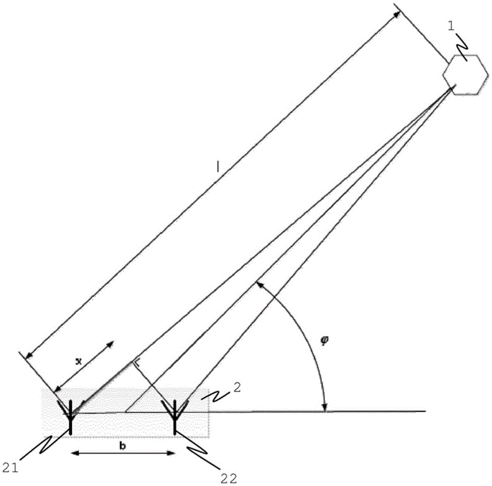
[0033] figure 1 The basic setup for the estimation of the angle of arrival of the signal originating from the tag 1 at the antennas 21 , 22 of the receiver 2 is shown. Tag 1 sends electromagnetic waves or pulses. The signal path l from the label to the left antenna 21 is longer than the path to the right antenna 22, as figure 1 shown. This path difference can be measured as the arrival time difference of the signals at the left antenna 21 and the right antenna 22 . Time difference can be converted to distance difference x, such as figure 1 shown. Under the condition that the distance from tag 1 to receiver 2 is greater than the distance b between the two receiving antennas 21, 22, the The following relationship holds for the distance x:

[0034]

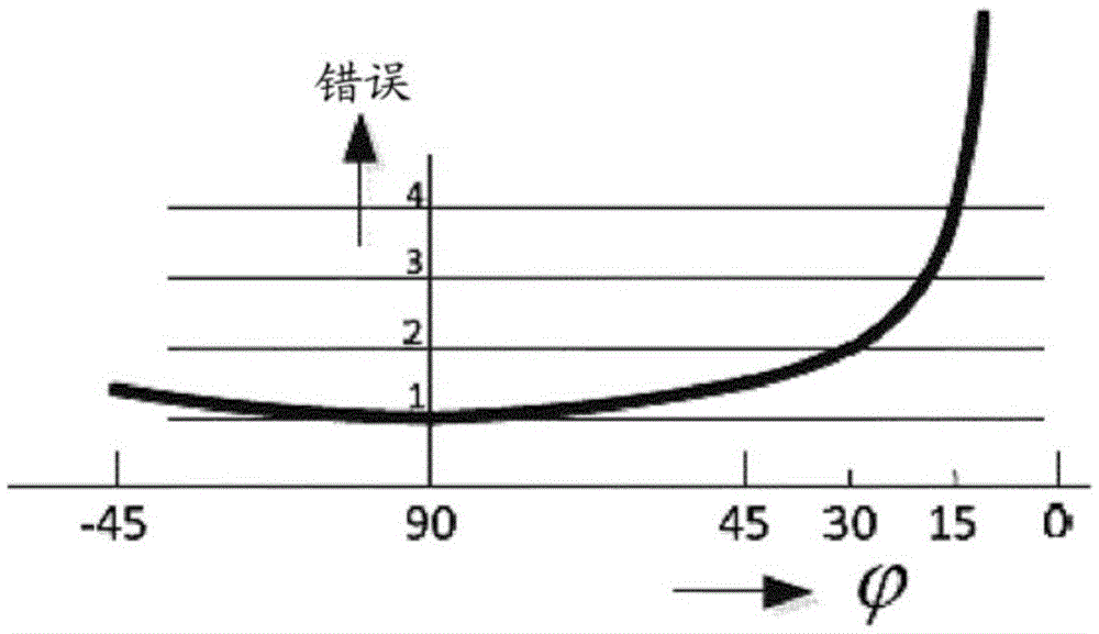
[0035] The inexactness of x will result in the angle error. can about x and The error leads to the following relationship:

[0036]

[0037] In Equation 2, Δx is the error in distance [m], is the error in angle [...


PUM


Abstract

A method and system are proposed for locating a tag. The system comprises a first receiver configured to receive a signal from a tag. The first receiver comprises at least two antennas each configured to receive the signal and a first processing means configured to calculate a first angle of arrival of the signal at the first receiver based on a distance between a first set of two antennas of the first receiver and a time difference of arrival of the signal at the two antennas of the first set. The tag comprises a tag antenna that is configured to transmit signals having a wide bandwidth and has a frequency independent phase center and wherein the signal is an ultra wideband signal comprising one or more pulses.

Description

technical field [0001] The present invention relates to locating and / or tracking tags in an area. More specifically, the present invention relates to a system for locating tags, a first receiver for use in a system for locating tags and a method for locating tags. Background technique [0002] Systems for locating and tracking nodes in an area are known. Solutions based on near-field ID cards and barcodes, for example, can provide snapshots at discrete moments, but cannot provide complete, up-to-date and accurate knowledge of a node's whereabouts. Systems based on eg WIFI, Bluetooth and Zigbee offer localization possibilities, but perform poorly in the vicinity of walls, people and water sources. This is due to the fact that these techniques operate in bandwidths that have been conceived for data transmission purposes, and they are incorrectly employed in poorly designed short-range tracking solutions. Other known GPS or GPRS / 3G solutions are expensive and only provide op...

Claims


Application Information

Patent Timeline
Patent Type & Authority Applications(China)
IPC IPC(8): G01S5/04G01S3/50G01S5/02
CPCG01S3/50G01S5/0205G01S5/04
Inventor S.I.弗拉迪米罗夫E.弗兰乔尼C.M.阿尔达威什-范基尔F.文图雷利
Owner BEESTAR BV
Why Eureka
Try Eureka