
Time-digital converter and time measuring device and method

A technology of time digital and time measurement, which is applied in the direction of electrical unknown time interval measurement, devices and instruments for measuring time intervals, etc. It can solve the problems of wasting production and testing time, unable to apply integrated circuits, and unable to catch signal anomalies and errors, etc. Achieve the effect of improving the efficiency and accuracy of production testing, facilitating large-scale production testing, and saving measurement time

Inactive Publication Date: 2015-04-22
HANGZHOU SILAN MICROELECTRONICS
View PDF5 Cites 7 Cited by
  • Summary
  • Abstract
  • Description
  • Claims
  • Application Information

AI Technical Summary

Problems solved by technology

[0005] Another method is to pass the signal through the delay line to calculate the delay time, but the defect of this method is that the abnormalities and errors in the measurement process cannot be found in time
Even if the signal to be tested is abnormal, the entire measurement process cannot be terminated, but the entire measurement process must be completed, which wastes valuable production test time and cannot catch signal anomalies and errors that occur during the measurement process.
Therefore, the time measurement method based on the delay line can only be used in the laboratory as an auxiliary test method for research, and cannot be applied in the large-scale integrated circuit production process at all.

Method used


Image

  • Time-digital converter and time measuring device and method
  • Time-digital converter and time measuring device and method
  • Time-digital converter and time measuring device and method

Examples


Embodiment Construction

[0045]Various embodiments of the invention will be described in more detail below with reference to the accompanying drawings. In the various drawings, the same elements are denoted by the same or similar reference numerals. For the sake of clarity, various parts in the drawings have not been drawn to scale.

[0046] The invention can be embodied in various forms, some examples of which are described below.

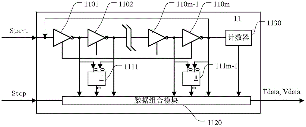
[0047] figure 1 is a schematic block diagram of a time-to-digital converter (TDC) according to the present invention. The time-to-digital converter 11 is used to measure the time interval between the start trigger signal (Start) and the stop trigger signal (Stop) of the signal to be measured, including:

[0048] M non-gates (1101-110m), the M non-gates are sequentially connected in series, the input end of the first non-gate 1101 in the M non-gates receives the initial trigger signal, and the M non-gate 110m The output terminal provides a counter trigger signal, and M...


PUM


Abstract

The invention discloses a time-digital converter which comprises M NOT gates sequentially connected in series. The input end of the first NOT gate receives starting triggering signals. The output end of the Mth NOT gate provides counter triggering signals. The first input ends and the second input ends of (M-1) exclusive-OR gates are connected with the output end of the corresponding NOT gate and the output end of the next NOT gate. A counter receives the counter triggering signals and counts the counter triggering signals. A data combination module is connected with the output ends of the M NOT gates, the output ends of the (M-1) exclusive-OR gate and the output end of the counter and receives termination triggering signals. Measuring data representing the time interval are generated according to the output of the M NOT gates and the output of the counter. Calibration data representing the measuring state are generated according to the (M-1) exclusive-OR gates. According to the time-digital converter, the tiny time interval between dynamic circuit signals can be accurately tested, meanwhile, the real-time calibration function is achieved, measurement abnormity and mistakes can be found in time, the follow-up measuring process is terminated, and the circuit testing and verification cost is saved.

Description

technical field [0001] The invention belongs to the field of integrated circuit testing, and in particular relates to a time-to-digital converter, a time measurement device and a measurement method thereof. Background technique [0002] In the whole process of integrated circuit research and development, trial production and mass production, it is necessary to use instruments and equipment with high precision and high performance to carry out meticulous and rigorous testing and verification of integrated circuits to ensure that the performance of the product can reach certain indicators and quality. A certain guarantee can be obtained, and at the same time, defective products can be effectively found and eliminated in the production process to ensure 100% shipment of integrated circuits that meet the standards. [0003] In integrated circuit testing, time measurement is an essential test item. For example, the measurement of the time interval between an integrated circuit r...

Claims


Application Information

Patent Timeline
Patent Type & Authority Applications(China)
IPC IPC(8): G04F10/04
Inventor 张明符强魏建中
Owner HANGZHOU SILAN MICROELECTRONICS
Learn More