Method for operating a braking system and a braking system

A technology of a braking system and a brake master cylinder, applied in the direction of brakes, etc., can solve the problems of not describing the braking auxiliary system, etc., and achieve the effect of reliable implementation and low cost.

Inactive Publication Date: 2016-06-22
CONTINENTAL TEVES AG & CO OHG
View PDF15 Cites 5 Cited by
  • Summary
  • Abstract
  • Description
  • Claims
  • Application Information

AI Technical Summary

Problems solved by technology

This document does not describe how the brake assist system can be reliably prevented from being activated incorrectly without a pressure sensor

Method used


Image

  • Method for operating a braking system and a braking system
  • Method for operating a braking system and a braking system

Examples


Embodiment Construction

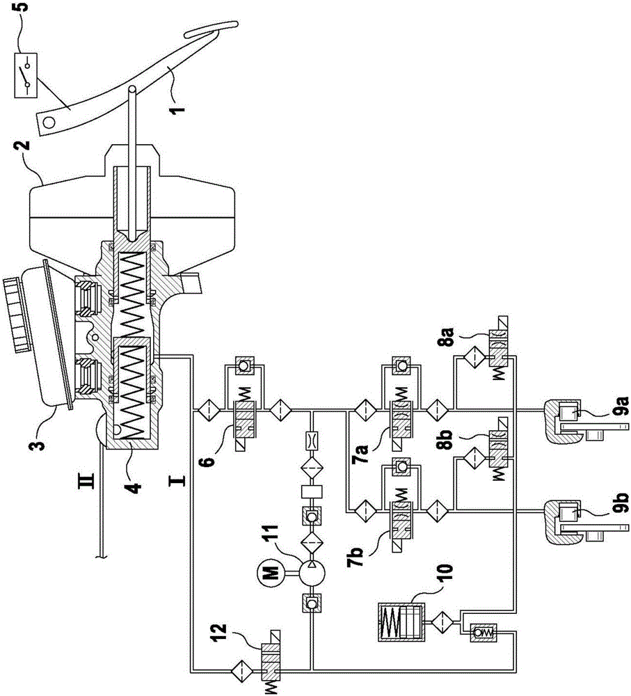
[0026] figure 1 An exemplary braking system of a motor vehicle is shown, with which the method according to the invention can be carried out. The driver-operated brake pedal 1 can be designed with or without auxiliary force support. The driver's braking force acts via the pressure lever, possibly superimposed with the auxiliary force generated by the low brake booster 2 , on the (tandem) brake master cylinder 4 , which is not actuated connected to an unpressurized brake fluid reservoir. Via the brake light switch 5 it can be determined whether the driver has actuated the brake pedal. As an alternative, the brake light switch can also be replaced by a travel sensor, which is arranged, for example, on the master brake cylinder 4 . The brake system has two brake circuits I, II, which (in the case of a four-wheeled vehicle) are each associated with two wheel brakes. Only brake circuit I will be described below, the other brake circuit II expediently having the same design. Th...


PUM


Abstract

The invention relates to a method for operating a brake system of a vehicle which comprises a master brake cylinder (4) which can be activated by the driver by means of a brake pedal (1), at least one driver-independent pressure source (11), at least one wheel brake (9a, 9b) to which a wheel speed sensor is assigned, and a brake activation sensor (5), wherein it is checked whether a hazardous situation is present, and in the case of a hazardous situation being detected the at least one driver-independent pressure source (11) is activated. According to the invention, a hazardous situation is detected when the change in a measured deceleration (a) over time or the absolute value of a measured deceleration (a) exceeds a predefined hazard threshold value (active) and a brake activation operation is detected. In addition, the invention relates to a brake system for a motor vehicle having brake assistance in hazardous situations ("brake assistant") which does not require a master brake cylinder pressure sensor.

Description

technical field [0001] The invention relates to a method according to the preamble of claim 1 and a braking system according to the preamble of claim 12 . Background technique [0002] Systems are known under the name "brake assist system" for assisting the driver's brake actuation, which, when a dangerous situation is detected, provide a rapid pressure build-up until the brake anti-skid control is activated and the current coefficient of friction is determined by This is optimally utilized. Dangerous situations are usually detected by means of a rapid brake actuation by the driver, which is expediently checked by means of the temporal gradient of the pressure in the brake master cylinder. A pressure sensor connected to the brake master cylinder is therefore required for a brake assistance system of the type known, for example, from DE 10137016 A1. With regard to driving safety, it is absolutely necessary to avoid erroneous activation of the brake assist (for example due t...

Claims


Application Information

Patent Timeline
Patent Type & Authority Applications(China)
IPC IPC(8): B60T8/32
CPCB60T8/3275B60T8/171B60T2201/03
Inventor A·纽T·乌尔里克T·舍勒R·施密特J·博尔内斯B·于斯特尔P·亨克
Owner CONTINENTAL TEVES AG & CO OHG
Why Eureka
Try Eureka