
Method of manufacturing thrust reverser cascades

a technology of thrust reverser and cascade, which is applied in the field of thrust reverser, can solve the problems of high labor intensity, high cost, and difficult process of layup process, and achieve the effect of reducing labor intensity, reducing production costs, and reducing production costs

Active Publication Date: 2016-09-15
UNITED TECH CORP +1
View PDF0 Cites 45 Cited by
  • Summary
  • Abstract
  • Description
  • Claims
  • Application Information

AI Technical Summary

Benefits of technology

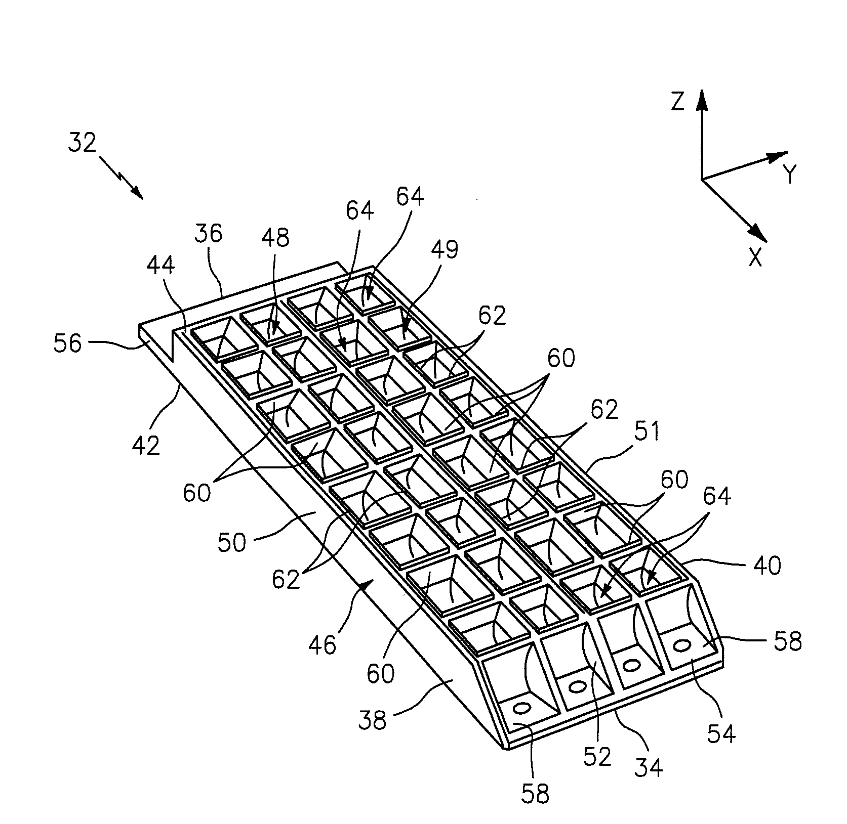
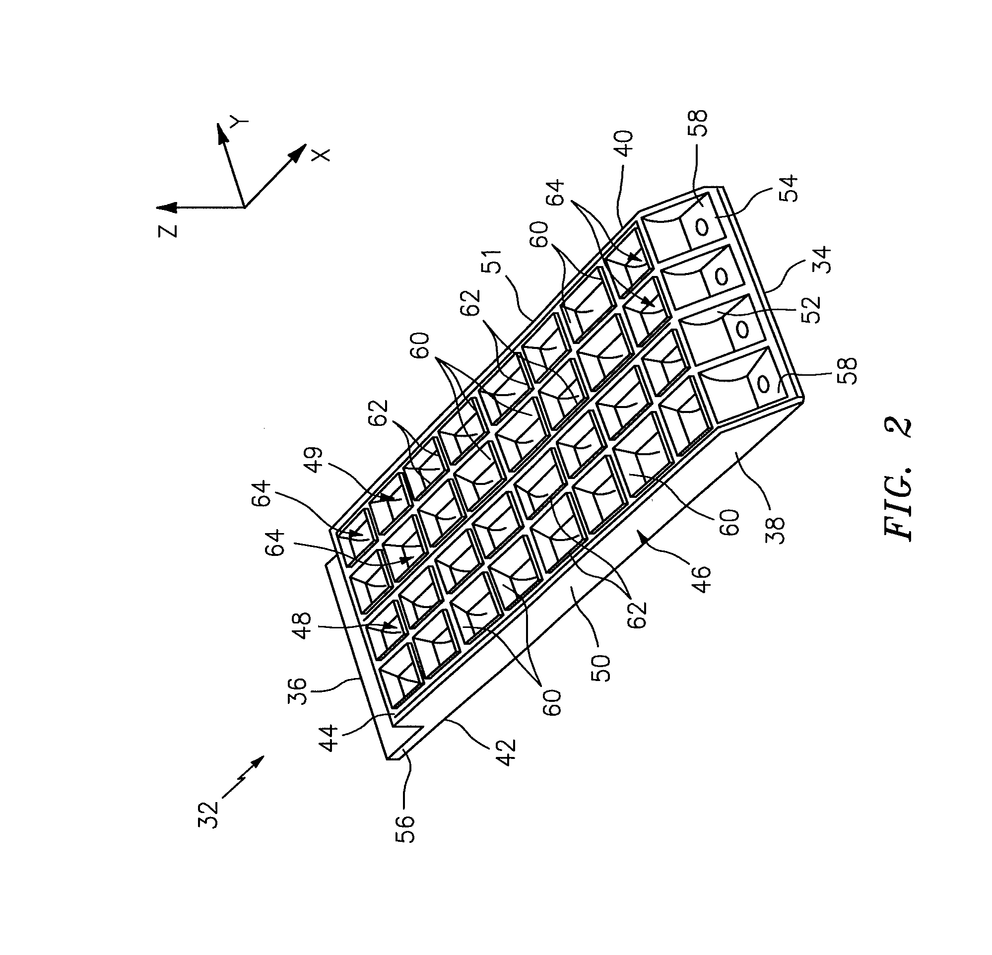
The invention provides methods for manufacturing a thrust reverser cascade, which is a component of an aircraft engine. The methods involve providing first and second cascade segments, which include a frame rail and an array of vane segments. The first and second cascade segments are bonded together, creating a thrust reverser cascade with a unique design. The technical effects of the invention include improved efficiency and reduced weight of the thrust reverser cascade, as well as improved performance and durability.

Problems solved by technology

The layup process is generally done by hand and is very labor intensive.
The process is very expensive and difficult.

Method used


Image

  • Method of manufacturing thrust reverser cascades
  • Method of manufacturing thrust reverser cascades
  • Method of manufacturing thrust reverser cascades

Examples


Embodiment Construction

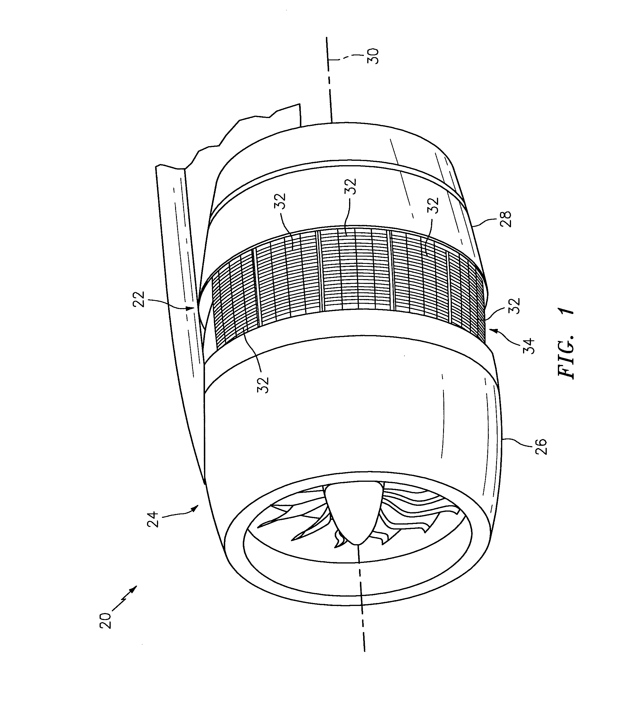
[0034]The present disclosure includes methods for manufacturing one or more cascades for a thrust reverser of an aircraft turbine engine propulsion system. An exemplary embodiment of such a propulsion system 20 and such a thrust reverser 22 is illustrated in FIG. 1. The methods of the present disclosure, of course, may also be utilized to manufacture thrust reverser cascades for different propulsion systems and cascades of different types and configurations other than those described herein.

[0035]The propulsion system 20 of FIG. 1 includes an outer (e.g., fan) nacelle 24 with a forward cowling 26 and a thrust reverser of the type having blocker doors, a cascade array, and a translating sleeve 28. One or more actuators are operable to translate the sleeve 28, for example generally along an axial centerline 30 of the propulsion system 20, between a first (e.g., stowed) position and a second (e.g., deployed) position as shown in FIG. 1.

[0036]The thrust reverser 22 of FIG. 1 includes an...


PUM


Abstract

Methods are provided for manufacturing a thrust reverser cascade. One of these methods includes providing a first cascade segment and providing a second cascade segment. The first cascade segment includes a first frame rail, a second frame rail and an array of first vane segments laterally between the first and the second frame rails. The second cascade segment includes an array of second vane segments. The second cascade segment is bonded laterally to and between the first and the second frame rails and transversely to the array of first vane segments. In another method, first and second cascade segments are discretely molded. Each of the cascade segments includes an array of vane segments and comprises fiber reinforcement in a polymer matrix. The second cascade segment is bonded to the first cascade segment and is nested into the first cascade segment.

Description

BACKGROUND[0001]1. Technical Field[0002]This disclosure relates generally to a thrust reverser for an aircraft propulsion system and, more particularly, to methods of forming cascades for a thrust reverser.[0003]2. Background Information[0004]A typical aircraft propulsion system such as a turbofan turbine engine may include a thrust reverser for redirecting bypass air forward to generate reverse thrust. Several types of thrust reversers are known in the art. Many of these thrust reversers include a cascade array, which provides a series of aerodynamic vanes for redirecting the bypass air in a desired forward direction during reverse thrust operation.[0005]Several methods have been used to manufacture cascades. Some exemplary methods include casting the cascade, machining the cascade, and fastening, welding or brazing cascade components such as vanes and strongback rails together. The foregoing methods, however, are most relevant to metallic cascades. Today, composite cascades are fa...

Claims


Application Information

Patent Timeline
IPC IPC(8): B29C65/00B29C70/06B29C65/30B29C65/48B29C65/32
CPCY02T50/67F02K1/56B29C66/301B29C65/48B29C65/32F02K1/64B29C70/06B29K2105/12B29L2031/7504B29L2031/3076B29D28/00B29C65/30F05D2230/20F05D2300/603Y02T50/60
Inventor KRUCKENBERG, TERESA
Owner UNITED TECH CORP
Learn More