Connector plug with flexible ridges and having a hook with a beveled surface

Active Publication Date: 2016-09-15
TECH HLDG
View PDF0 Cites 1 Cited by
  • Summary
  • Abstract
  • Description
  • Claims
  • Application Information

AI Technical Summary

Benefits of technology

[0003]According to embodiments of the present disclosure, disadvantages a

Problems solved by technology

Electrical and mechanical devices often need to be placed in hard to reach locations where they may be exposed to adverse weather conditions, moisture,

Method used


Image

  • Connector plug with flexible ridges and having a hook with a beveled surface
  • Connector plug with flexible ridges and having a hook with a beveled surface
  • Connector plug with flexible ridges and having a hook with a beveled surface

Examples


Example

DETAILED DESCRIPTION OF THE DRAWINGS

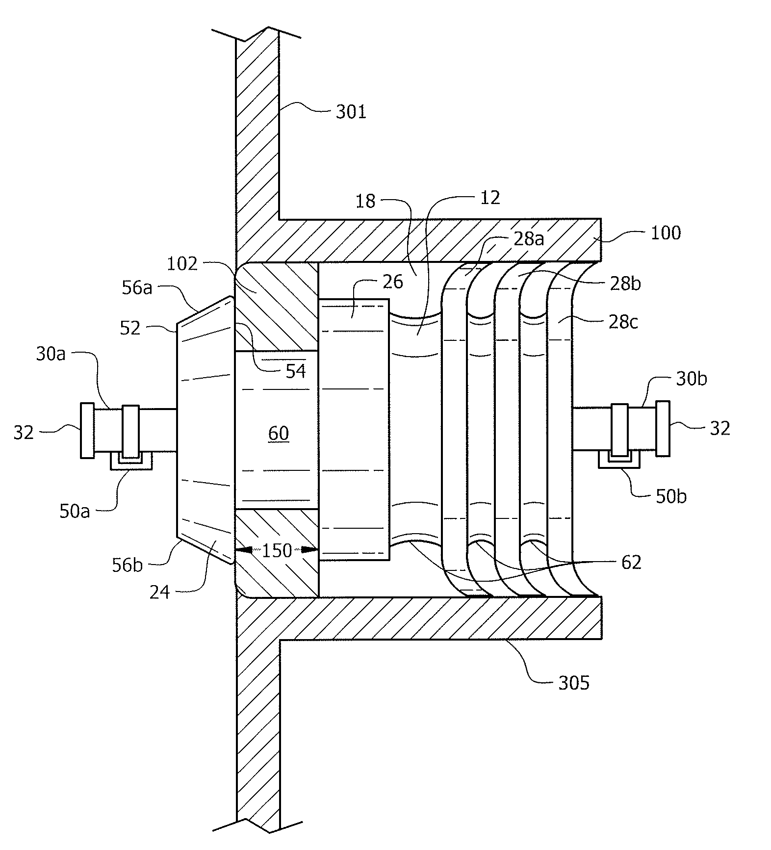
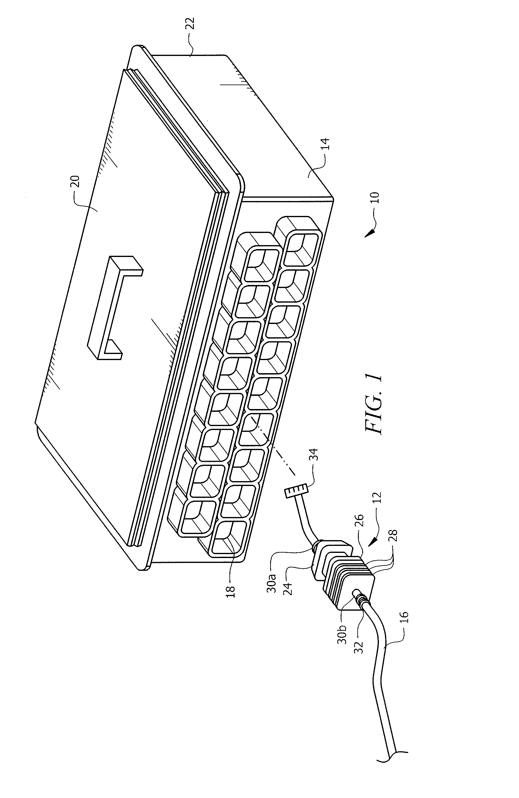
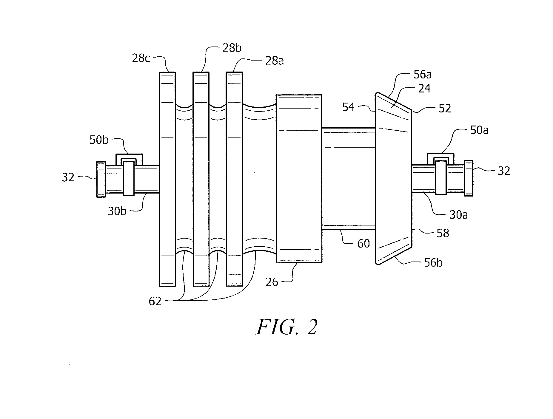
[0012]FIG. 1 illustrates a system 10 comprising a connector plug 12 and a housing 14 according to certain embodiments of the present disclosure. Housing 14 comprises a body portion 22 having multiple openings 18 formed therein. Housing 14 may further comprise a top portion 20, such as a lid, that encloses housing 14. Connector plug 12 may be removably coupled to housing 14 by inserting connector plug 12 into an opening 18 of the housing 14 while housing 14 remains intact. In other words, connector plug 12 may be inserted into opening 18 while top portion 20 is closed, the opening 18 remains intact, or top portion 20 and body portion 22 of housing 14 otherwise remain attached to each other to form an enclosure. Connector plug 12 may also be removed from opening 18 of housing 14 while housing 14 remains intact. In other words, connector plug 12 can be removed from opening 18 of housing 14 while top portion 20 is closed, the opening 18 remains intact...


PUM


Abstract

A connector plug comprises a hook with flexible edges. The hook has a first beveled surface and a second flat surface. A stopper is coupled to the flat surface of the hook by a first barrel portion of the connector plug. The stopper is coupled to a plurality of ridges with flexible edges by a second barrel portion. The plurality of ridges are also coupled to each other by the second barrel portion. A via extends through the connector plug from one end of the connector plug to the other end of the connector plug.

Description

TECHNICAL FIELD[0001]This disclosure relates generally to mechanical devices and specifically to a connector plug for a housing.BACKGROUND OF THE INVENTION[0002]Electrical and mechanical devices often need to be placed in hard to reach locations where they may be exposed to adverse weather conditions, moisture, contaminants, or other foreign objects that could damage them. It is thus desirable to keep these devices protected while at the same time accessible and easy to maintain. Current approaches to solving this problem are ineffective and generally difficult to use.SUMMARY OF THE INVENTION[0003]According to embodiments of the present disclosure, disadvantages and problems associated with previous devices may be reduced or eliminated.[0004]In one embodiment, a connector plug comprises a hook with flexible edges. The hook has a first beveled surface and a second flat surface. A stopper is coupled to the flat surface of the hook by a first barrel portion of the connector plug. The s...

Claims


Application Information

Patent Timeline
IPC IPC(8): H01R13/502H01R25/00
CPCH01R13/502H01R13/5205H01R25/00H01R13/5208H02G3/083H02G15/007H02G15/013
Inventor MADINABEITIA, RAFAEL ANTONIO FEMATTJASSO, JORGE L. MIRELES
Owner TECH HLDG
Why Eureka
Try Eureka