Vehicle seat air-conditioning device

a technology for air-conditioning devices and seats, which is applied in vehicle heating/cooling devices, seat heating/ventilation devices, vehicle arrangements, etc., to achieve the effect of improving the comfort of the seated occupan

Active Publication Date: 2016-09-22
DENSO CORP
View PDF3 Cites 27 Cited by
  • Summary
  • Abstract
  • Description
  • Claims
  • Application Information

AI Technical Summary

Benefits of technology

[0006]In Patent Literature 1, a technique is described in which the air-conditioning capacity of a vehicle seat air-conditioning device is changed based on a build which is the size of the body of a passenger. Here, if the build or the sitting position of the seated occupant changes, then the wind direction of blowout air that feels pleasant to the seat occupant also changes. Accordingly, when viewed from a poin

Problems solved by technology

However, the vehicle seat air-conditioning device of Patent Literature 1 do

Method used


Image

  • Vehicle seat air-conditioning device
  • Vehicle seat air-conditioning device
  • Vehicle seat air-conditioning device

Examples


first embodiment

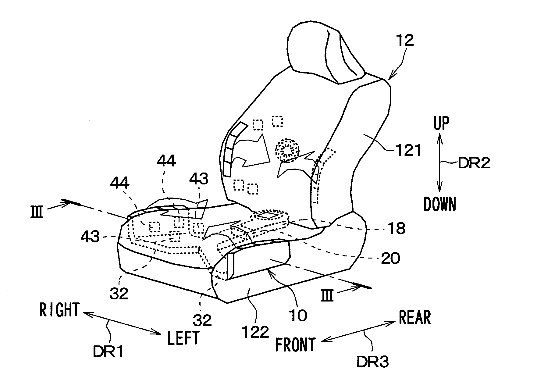
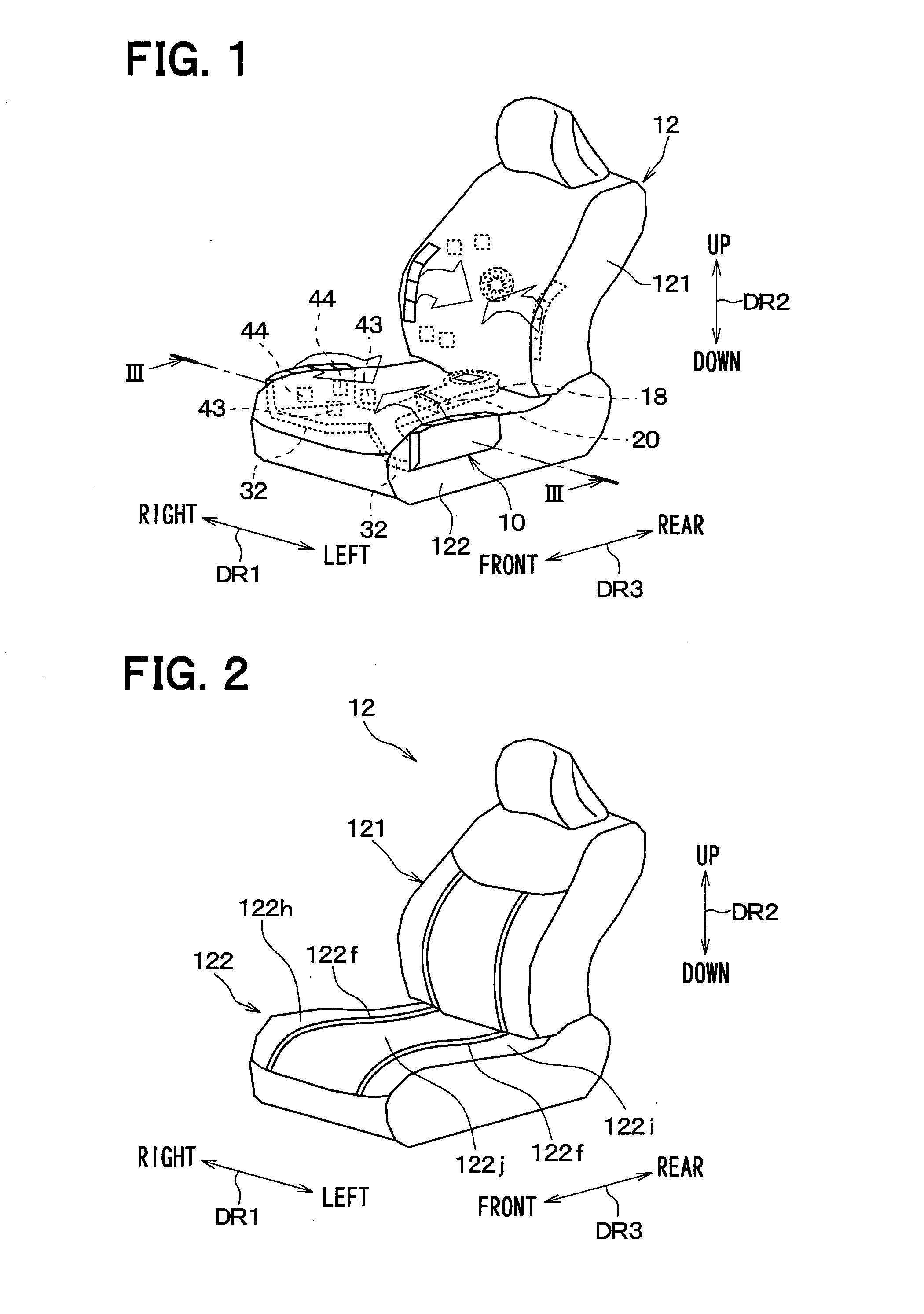
[0021]FIG. 1 is an outline perspective view showing a vehicle seat air-conditioning device 10 of the present embodiment, and showing a vehicle seat 12 having the vehicle seat air-conditioning device 10 installed. Each of a seat back 121 and a seat cushion 122 of the vehicle seat 12 has a vehicle seat air-conditioning device installed, but the vehicle seat air-conditioning device 10 of the present disclosure (hereinafter, simply “seat air-conditioning device 10”) is a vehicle seat air-conditioning device installed in the seat cushion 122. Further, in FIG. 1, the directional market DR1 shows a left-right direction DR1 of the vehicle, i.e., is a vehicle width direction DR1. The directional market DR2 shows an up-down direction DR2 of the vehicle, i.e., is a vehicle vertical direction DR2. The directional market DR3 shows a front-rear direction of the vehicle, i.e., is a vehicle longitudinal direction DR3

[0022]The vehicle seat 12 shown in FIG. 1 includes the seat back 121 and the seat c...

second embodiment

[0066]Next, a second embodiment of the present disclosure will be explained. In the present embodiment, an explanation will be focused on points which differ from the previously discussed first embodiment, and portions which are the same as, or equivalent to, those of the first embodiment will be omitted or simplified. The same applies to the third embodiment discussed later.

[0067]FIG. 7 is a cross sectional view of a seat cushion 122 and a seat air-conditioning device 10 according to the present embodiment, and corresponds to FIG. 3 of the first embodiment. As shown in FIG. 7, the blowout ventilation pipe 32 of the present embodiment does not wrap around the sides of the seat cushion 122, and the blowout ventilation pipe 32 does not have the air blowout portion 321 (refer to FIG. 3). An end portion 322 of the blowout ventilation pipe 32, which is at an opposite end from the heat exchanger 20 side, is connected from the bottom of the seat cushion 122 to a first ventilation passage 1...

third embodiment

[0077]Next, a third embodiment of the present disclosure will be explained. In the present embodiment, an explanation will be focused on points which differ from the previously discussed first embodiment.

[0078]FIG. 8 is an outline perspective view of a vehicle seat air-conditioning device 10 and a vehicle seat 12 that has the vehicle seat air-conditioning device 10 installed, according to the present embodiment. As shown in FIG. 8, when compared with the first embodiment, the arrangement position of the air blowout portion 321 in the present embodiment is different. Specifically, the air blowout portion 321 is positioned such that the air-conditioned air from the air blowout portion 321 is blown toward the lower legs of the seated occupant. The blowing direction changing device 24 disposed in the air blowout portion 321 is able to change the air blowing direction of the air blowout portion 321, shown as the arrows AR1wd, AR2wd, in the vehicle width direction DR1 as shown by the arro...


PUM


Abstract

A seat air-conditioning device is provided with an air blowout portion which is open so as to blow out air toward a seated occupant seated on a vehicle seat, the air being blown from a ventilator. A control device of the seat air-conditioning device causes a blowing direction changing device to change a blowing direction of the air blown our from the air blowout portion based on passenger information including a build and a sitting position of a passenger which is the seated occupant. Accordingly, air can be blown in a direction according to the build or the sitting position of the seated occupant.

Description

CROSS-REFERENCE TO RELATED APPLICATION[0001]The present application is based on Japanese patent application No. 2013-222119 filed on Oct. 25, 2013, the content of which is incorporated herein by reference.TECHNICAL FIELD[0002]The present disclosure relates to a vehicle seat air-conditioning device that blows out conditioned air in a vehicle seat.BACKGROUND ART[0003]As a conventional technology related to vehicle seat air-conditioning devices, for example there is the device disclosed in Patent Literature 1. A vehicle seat air-conditioning device of Patent Literature 1 includes an air-conditioning device formed of a ventilator and a heat exchanger disposed in a vehicle seat, a camera that photographs a seated occupant who is a passenger sitting in the vehicle seat, and a controller that controls the air-conditioning device.[0004]Then, the controller sets the operation of the air-conditioning device to a normal mode when the size of the body of the passenger, which is obtained based o...

Claims


Application Information

Patent Timeline
IPC IPC(8): B60H1/00B60N2/56
CPCB60H1/00285B60H1/00742B60H2001/00128B60N2/56B60H2001/003B60H1/00871B60N2/5657
Inventor TANAKA, YUUSUKENIIMI, YASUHIKOFUJII, TAKAHISA
Owner DENSO CORP
Why Eureka
Try Eureka