Ventilator with integrated oxygen production

a technology of ventilation device and oxygen production, applied in the field of ventilation device, can solve the problem of particularly problematic travel with such equipmen

Active Publication Date: 2016-09-29
VENTEC LIFE SYST INC
View PDF15 Cites 21 Cited by
  • Summary
  • Abstract
  • Description
  • Claims
  • Application Information

AI Technical Summary

Benefits of technology

[0020]An embodiment includes a ventilator device for use with an oxygen source and a patient circuit. The patient circuit is configured to receive breathing gases and oxygen to provide a breath to a human patient having a patient connection couplable to the patient circuit. The breath has an inspiratory phase with a beginning and an end. The ventilator device includes a compressor configured to deliver breathing gases to the patient circuit, and a control system configured to (a) allow the oxygen to flow from the oxygen source to the patient circuit at or before a beginning of an inspiratory phase of a breath, (b) prevent the oxygen from flowing from the oxygen source to the patient circuit before an end of the inspiratory phase of the breath, and (c) cause the compressor to deliver the breathing gases to the patient circuit before the end of the inspiratory phase of the breath.

Problems solved by technology

Thus, in additional to a ventilator, many patients require multiple devices and traveling with such equipment can be particularly problematic.

Method used


Image

  • Ventilator with integrated oxygen production
  • Ventilator with integrated oxygen production
  • Ventilator with integrated oxygen production

Examples


first embodiment

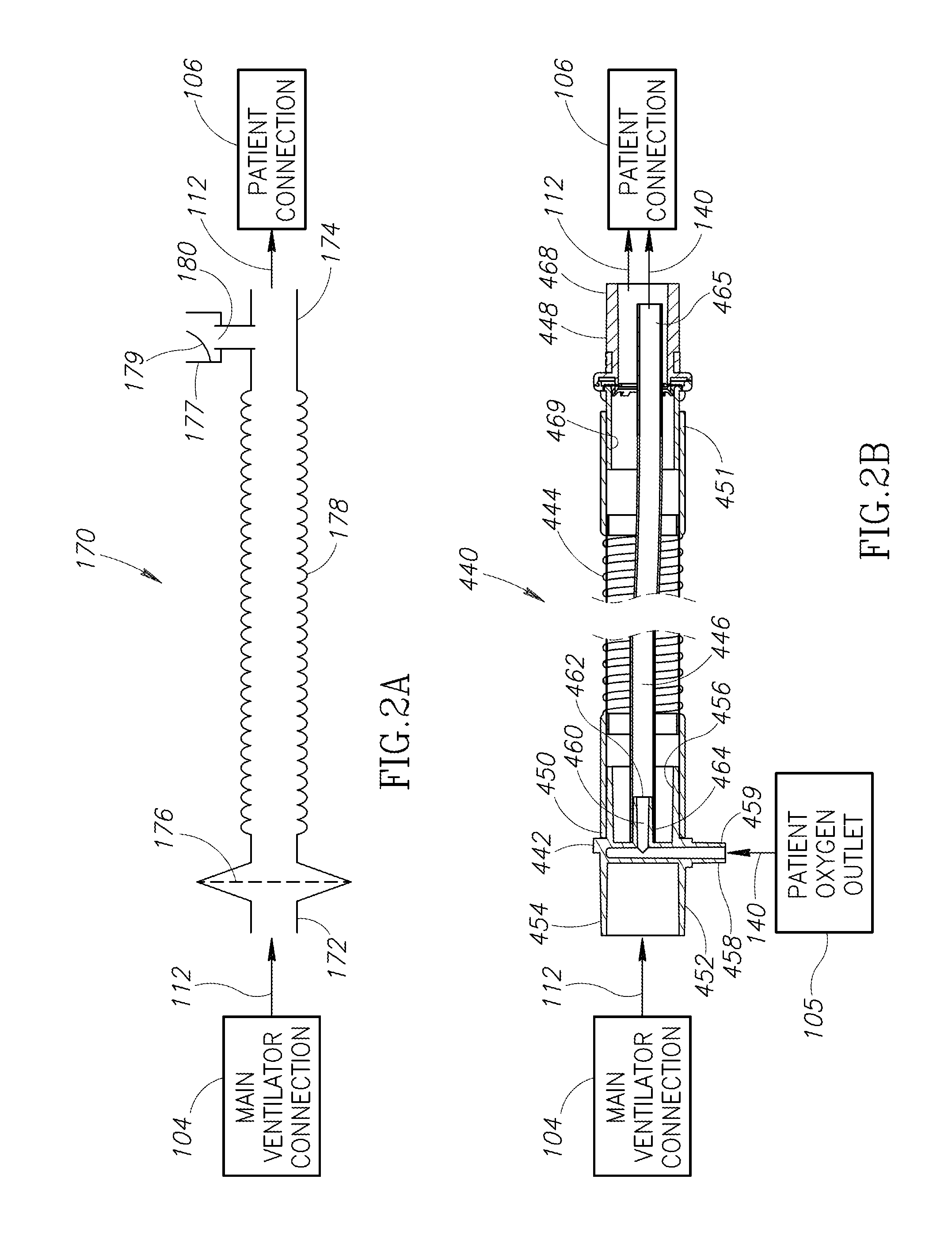
[0082]FIG. 2A is an illustration of a passive patient circuit 170 that may be used to implement the patient circuit 110. Referring to FIG. 2A, the passive patient circuit 170 has a first end portion 172 opposite a second end portion 174. The first end portion 172 is configured to be connected or coupled (e.g., directly or using a hose, flow line, conduit, or tube) to the main ventilator connection 104. The second end portion 174 is configured to be connected or coupled to the patient connection 106 (e.g., directly or using a hose, flow line, conduit, or tube). The passive patient circuit 170 conducts the gases 112 (that include the air 114 optionally mixed with oxygen) from the main ventilator connection 104 into the patient connection 106.

[0083]In the embodiment illustrated, the passive patient circuit 170 includes an optional bacterial filter 176, a leak valve 177, and a flexible tube segment 178. The optional bacterial filter 176 may be positioned between the first end portion 17...

second embodiment

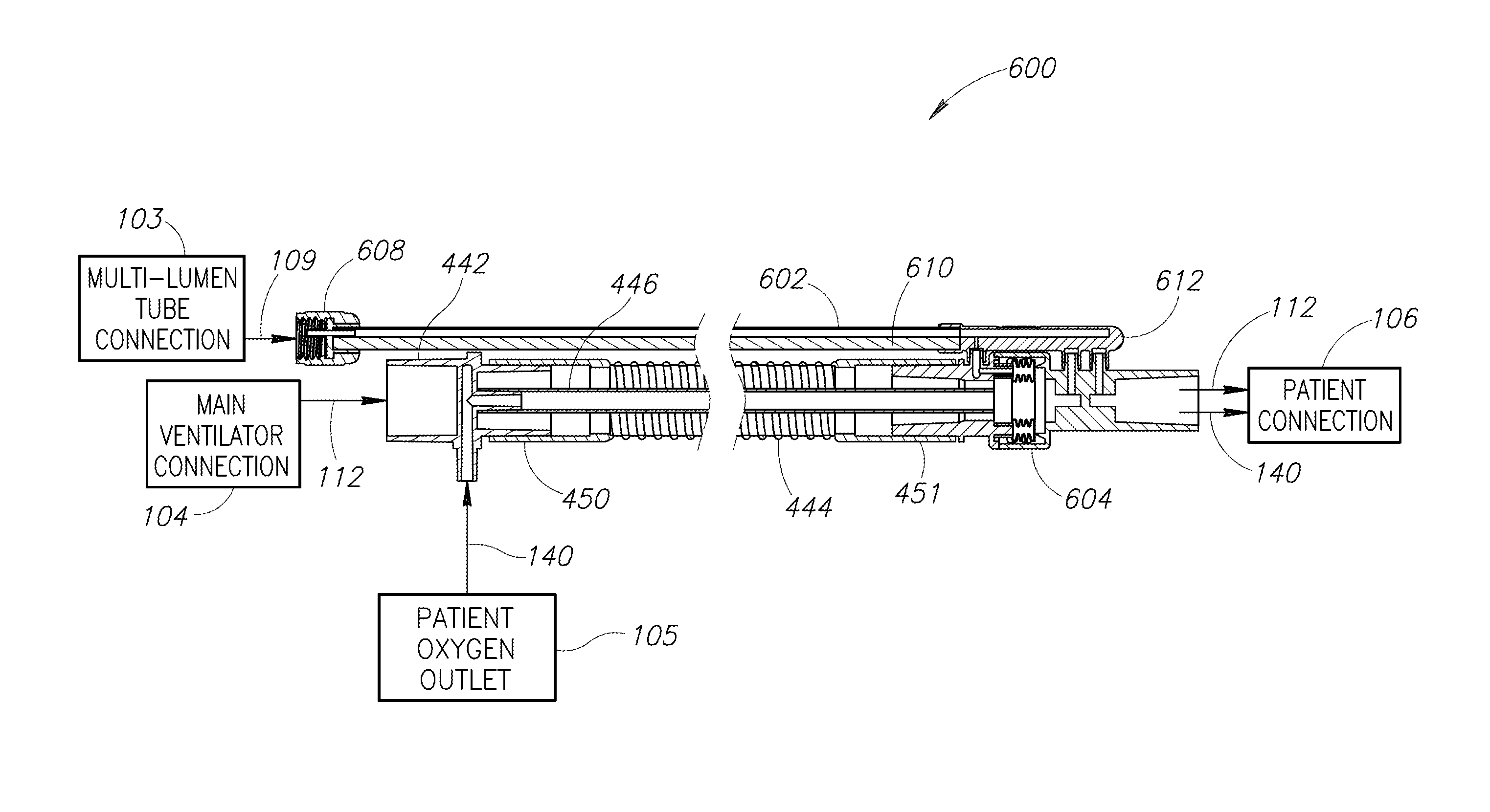
[0087]FIG. 2B is an illustration of a passive patient circuit 440 that may be used to implement the patient circuit 110. The passive patient circuit 440 includes a connector 442, a flexible tube segment 444, an open-ended oxygen pulse delivery tube 446, and a valve assembly 448. The flexible tube segment 444 may be implemented using a conventional corrugated or expanding ventilation hose or tubing (e.g., circuit tubing). The flexible tube segment 444 has a first end portion 450 opposite a second end portion 451. The first end portion 450 is configured to be connected or coupled to the connector 442. The second end portion 451 is configured to be connected or coupled to the valve assembly 448.

[0088]The connector 442 has a generally tube-shaped connector housing 452 with a first end portion 454 configured to be connected to the main ventilator connection 104 (e.g., directly or using a hose, flow line, conduit, or tube) and to receive the gases 112 (that include the air 114 optionally ...


PUM


Abstract

A method of providing a breath to a human patient having a patient connection connected by a patient circuit to a ventilator device. The method includes delivering both a bolus of oxygen and breathing gases including air to the patient circuit. The patient circuit conducts the bolus of oxygen and the breathing gases to the patient connection. The breathing gases are delivered before an end of the inspiratory phase of the breath. The bolus may be delivered at or before a beginning of an inspiratory phase of the breath, and the delivery of the bolus may be terminated before the end of the inspiratory phase of the breath. The bolus and breathing gases are delivered to the patient circuit via different ventilator connections that isolate the bolus from the breathing gases before they enter the patient circuit.

Description

BACKGROUND OF THE INVENTION[0001]1. Field of the Invention[0002]The present invention is directed generally to ventilators used to assist human patients with breathing.[0003]2. Description of the Related Art[0004]Respiration may be characterized as including both an inspiratory phase and an exhalation phase. During the inspiratory phase, inspiratory gases are drawn into the lungs, and during the exhalation phase, exhalation gases are expelled from the lungs.[0005]Mechanical ventilators are used to assist with breathing. Conventional ventilators typically push inspiratory gases including oxygen into the patient's lungs. Many patients who use a ventilator also need other types of assistance related to treating and maintaining their airways and lungs. For example, some patients may use a nebulizer to deliver drugs to their lungs and / or airways. Further, some patients may need help clearing secretions from their lungs and / or airways. Such assistance is typically provided by a convention...

Claims


Application Information

Patent Timeline
Patent Type & Authority Applications(United States)
IPC IPC(8): A61M16/00A61M16/06A61M16/20A61M16/04
CPCA61M16/0069A61M16/0003A61M16/0063A61M16/04A61M2205/52A61M16/20A61M2202/0208A61M2205/3334A61M16/0666A61M16/201A61M16/00A61M16/10A61M16/0051A61M2016/0027A61M2016/0036A61M2016/0039A61M2016/1025A61M2205/3358A61M2205/42A61M16/0858B01D53/0476B01D2259/401A61M16/1055A61M16/107A61M16/024A61M16/0009A61M16/0875A61M16/101B01D53/053B01D2256/12B01D2257/102B01D2259/40009B01D2259/4533A61M16/202A61M2205/0272A61M2202/0007A61M16/0883A61M16/207A61M16/0057A61M16/0808A61M16/0816A61M16/208A61M2205/502
Inventor DEVRIES, DOUGLAS F.GOOD, DAVID M.GAW, SHAN E.CIPOLLONE, JOSEPHBRANSON, RICHARD
Owner VENTEC LIFE SYST INC
Why Eureka
Try Eureka