Air Data Probe With Improved Performance at Angle of Attack Operation

Active Publication Date: 2016-09-29
ROSEMOUNT AEROSPACE
View PDF9 Cites 0 Cited by
  • Summary
  • Abstract
  • Description
  • Claims
  • Application Information

AI Technical Summary

Benefits of technology

The patent text describes an air data probe that has a pitot tube with a tap at the front. This tap has a narrow inner flow path that decreases in size as it reaches a throat. The inner flow path is designed in a specific shape, which can also include sections of removed material. The technical effect of this design is to improve the accuracy and reliability of air data measurements for aircraft navigation.

Problems solved by technology

The requirements for such air data probes are challenging, especially when utilized in environments including ice crystals.
For the air data probe to provide accurate information, total pressure recovery requirements remain unchanged and, thus, the air recirculation and boundary layer separation raise challenges.
The challenges mentioned above with regard to recirculation and boundary layer separation occur adjacent to the pitot tube tap.

Method used


Image

  • Air Data Probe With Improved Performance at Angle of Attack Operation
  • Air Data Probe With Improved Performance at Angle of Attack Operation
  • Air Data Probe With Improved Performance at Angle of Attack Operation

Examples


embodiment 46

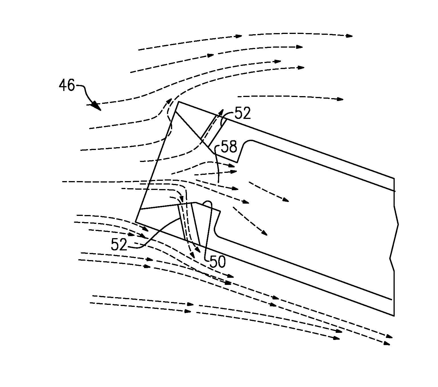
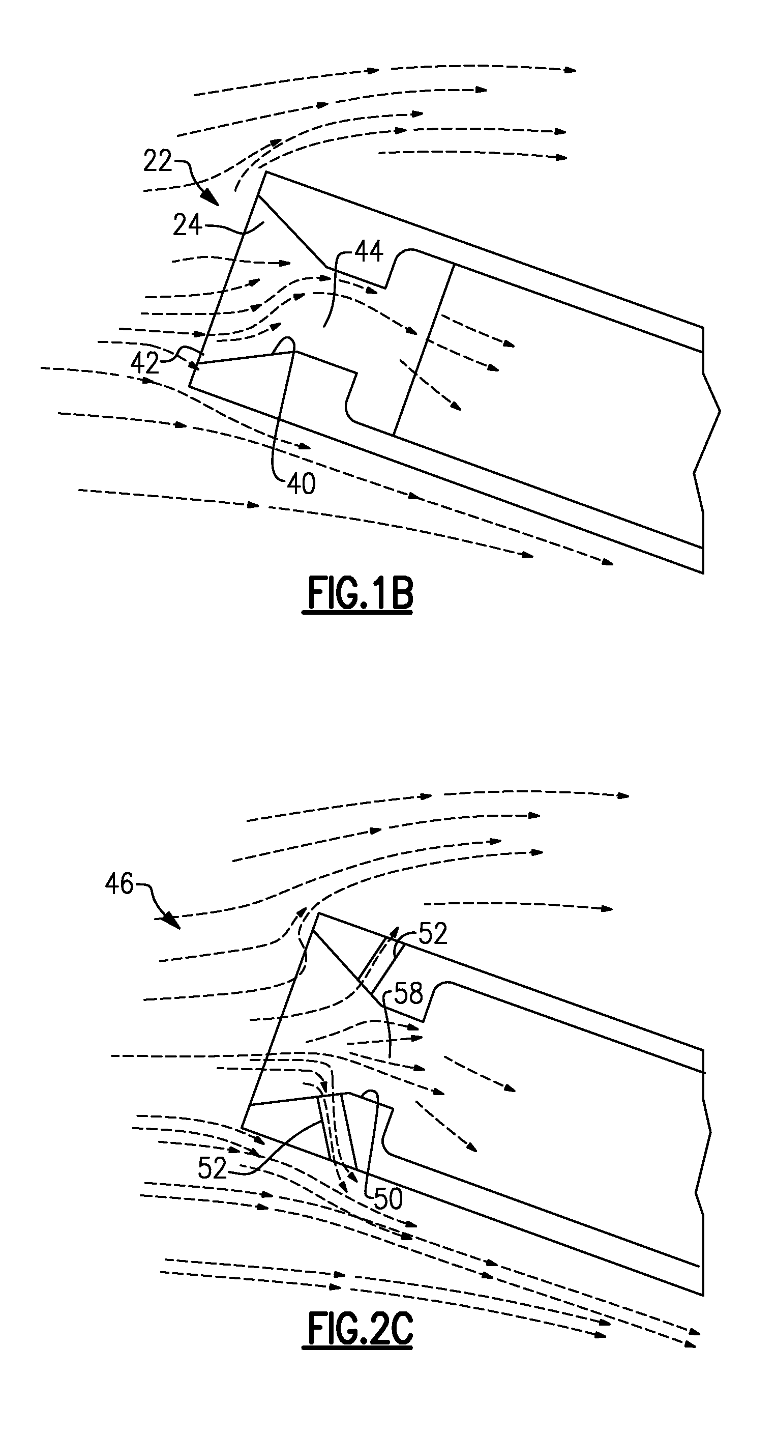
[0019]FIG. 2A shows an embodiment 46 wherein the tap 47 extends from an outer end 48 inwardly toward a throat 50. A plurality of bleed holes 52 extend through a body of the air data probe 46 from an outlet 54 at an outer peripheral surface to an inlet 56 at an inner surface 57. Inner surface 57 of the air data probe 46 extends from the outer end 48 at an angle that decreases the cross-sectional area of an inner flow path as it moves inwardly until it reaches the throat 50. The bleed hole 52 has inlet 56 upstream of the throat 50.

[0020]FIG. 2B is a view showing a plurality of bleed holes 52. The quantity, size and location of the bleed holes 52 may be selected for specific operation in a particular environment.

[0021]FIG. 2C shows the operation of the air data probe 46. Air entering through the bleed holes 52 leaves the inner flow path, eliminating the recirculation and boundary layer separation illustrated in FIG. 1B. As shown, there is now uniform flow.

embodiment 60

[0022]FIG. 3A shows an embodiment 60 wherein the tap 62 has a forward end 66 with a fluted slot with a circumferentially thin portion 64 leading into a circumferentially enlarged opening 68. Other areas 70 of the tap 62 do not have the slots 64 / 68.

[0023]As shown in FIG. 3B, there are slots 64 / 68 on opposed sides with intermediate generally cylindrical portions 70. Notably, the slots 64 / 68 end at the throat 72.

[0024]The slots 64 / 68 assist in bringing air in to reduce recirculation and boundary layer separation, similar to the FIG. 2A-2C embodiment.

[0025]Generically, the FIGS. 2A-2C and FIGS. 3A, 3B embodiments could be said to have removed material to assist in providing additional air pressure.

[0026]The FIGS. 2A-2C, and FIGS. 3A / 3B embodiment could be said to have a pitot tube with a tap at a forward end, and defining an inner flow path. The inner flow path decreases in cross-sectional area until reaching a throat. The inner flow path has cross-sections which are generally cylindric...

embodiment 74

[0027]FIG. 4B shows yet another embodiment 74. Embodiment 74 could be seen as a “long nose” air data probe. A nose 76 is provided with a relatively small diameter d1. The diameter d1 extends through a long nose that is generally straight or slightly tapered across a distance d2. At an enlarged area 78, the diameter begins to increase to provide room for receiving a heater element 80. The enlarged area 78 is at a diameter d3. A bleed hole 82 may be incorporated much like the FIG. 2A-2C embodiments.

[0028]In embodiments, a relationship exists between the ratio of d3 / di to d2. The d3 quantity is controlled by physical characteristics of the probe tube and the heater element 80. The d1 quantity is controlled by environmental conditions in which the probe is required to operate.

[0029]A ratio of d1 to d3 identifies how long d2 should be. Applicant has discovered a constant that is associated with the relationship of the three quantities. Thus, the following relationship preferably applies:...


PUM


Abstract

An air data probe has a pitot tube with a tap at a forward end that defines an inner flow path. The inner flow path decreases in the cross-sectional area until reaching a throat. The inner flow path has cross-sections that are generally cylindrical and also has sections of removed material. Other embodiment have unique shapes.

Description

BACKGROUND OF THE INVENTION[0001]This application relates to an air data probe for use in aircraft applications wherein its performance is improved during certain operational conditions of an associated aircraft.[0002]Modern aircraft are becoming more sophisticated and require precise information. Controls for modern aircraft must know an air speed with accuracy. As part of determining the air speed, an air data probe is often mounted on an aircraft body.[0003]Air data probes take in air and evaluate that air to determine air speed and other parameters (as examples, altitude, angle of attack, angle of sideslip of an aircraft carrying the probe, etc.).[0004]The requirements for such air data probes are challenging, especially when utilized in environments including ice crystals. Also, when an associated aircraft is operating at a pronounced angle of attack, air recirculation and boundary layers separation may incur within an opening or tap into the air data probe. For the air data pr...

Claims


Application Information

Patent Timeline
IPC IPC(8): G01F1/46B64D45/00
CPCB64D45/00G01F1/46G01P5/165
Inventor JOHNSON, PAUL ROBERTCUSHER, AARON A.GOLLY, TIMOTHY THOMASMATHEIS, BRIAN DANIELSEIDEL, GREG
Owner ROSEMOUNT AEROSPACE
Why Eureka
Try Eureka