Premixed Fuel Nozzle

Active Publication Date: 2020-06-04
GENERAL ELECTRIC CO
View PDF6 Cites 4 Cited by
  • Summary
  • Abstract
  • Description
  • Claims
  • Application Information

AI Technical Summary

Benefits of technology

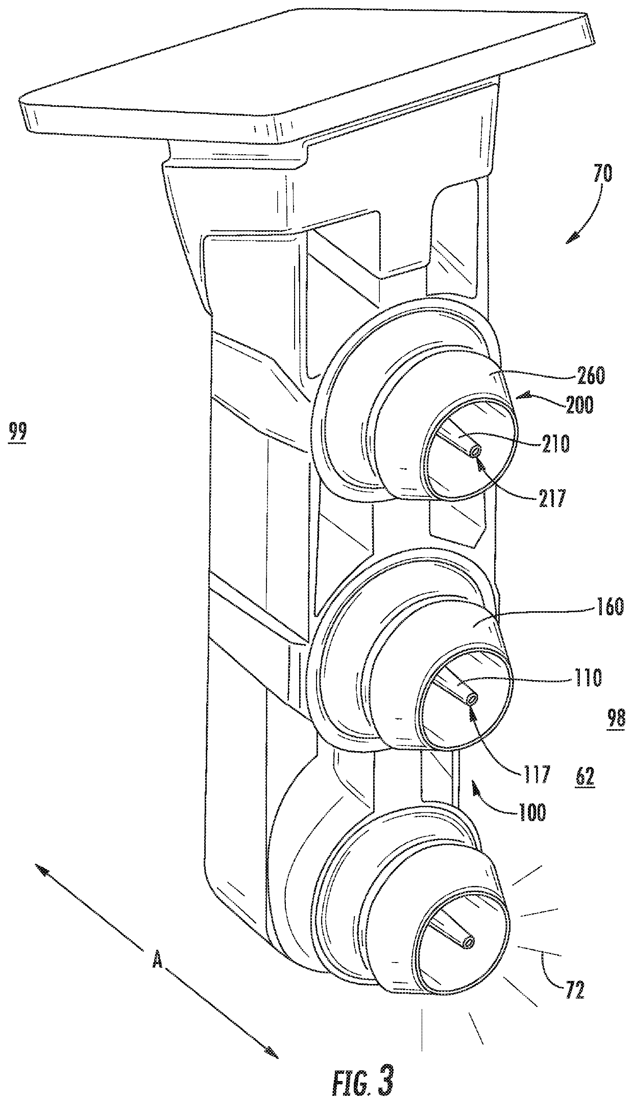
[0014]In one embodiment, the first centerbody defines a throat area between the cooling circuit and the axially extended cooling outlet. The cooling outlet defines an increasing cross sectional area from the throat area to the downstream end of the first centerbody.
[0015]In various embodiments, the first fuel injector further comprises an internal shroud disposed within the first cente

Problems solved by technology

In high temperature combustion, such as above approximately 1530 C, NOx is produced in more significant quantities that present challenges for gas turbine engine design and operation.
Known structures and methods of NOx reduction in fuel injection and combustion systems are generally limited by other design criteria, including maintaining combustion stability (e.g., mitigating lean blow out) across the operating range of the engine, mitigating undesired combustion dynamics (e.g., pressure oscillations resulting from heat release during combustion), the resulting pattern factor (e.g., circumferential variations in combusti

Method used


Image

  • Premixed Fuel Nozzle
  • Premixed Fuel Nozzle
  • Premixed Fuel Nozzle

Examples


Example

[0029]Repeat use of reference characters in the present specification and drawings is intended to represent the same or analogous features or elements of the present invention.

DETAILED DESCRIPTION

[0030]Reference now will be made in detail to embodiments of the invention, one or more examples of which are illustrated in the drawings. Each example is provided by way of explanation of the invention, not limitation of the invention. In fact, it will be apparent to those skilled in the art that various modifications and variations can be made in the present invention without departing from the scope or spirit of the invention. For instance, features illustrated or described as part of one embodiment can be used with another embodiment to yield a still further embodiment. Thus, it is intended that the present invention covers such modifications and variations as come within the scope of the appended claims and their equivalents.

[0031]As used herein, the terms “first”, “second”, and “third...


PUM


Abstract

A fuel injector assembly for a gas turbine engine is generally provided. The first fuel injector includes a first centerbody surrounding a first walled fuel injection circuit. A first fuel injection port is extended at least partially radially through the first centerbody in fluid communication with the first walled fuel injection circuit. The first centerbody defines a cooling circuit surrounding the first walled fuel injection circuit. The first centerbody defines a plurality of cooling openings at a downstream end of the first centerbody. The plurality of cooling openings is in fluid communication with the cooling circuit. The first centerbody defines an axially extended cooling outlet at the downstream end of the first centerbody.

Description

FIELD[0001]The present subject matter relates generally to gas turbine engine fuel injector and combustor assemblies.BACKGROUND[0002]Gas turbine engines are generally challenged to reduce emissions such as oxides of nitrogen (NOx) formed due to the presence of nitrogen and oxygen at elevated temperatures during combustion. In high temperature combustion, such as above approximately 1530 C, NOx is produced in more significant quantities that present challenges for gas turbine engine design and operation. Above approximately 1530 C, the rate of NOx formation rapidly increases with further rises in combustion temperature.[0003]Known structures and methods of NOx reduction in fuel injection and combustion systems are generally limited by other design criteria, including maintaining combustion stability (e.g., mitigating lean blow out) across the operating range of the engine, mitigating undesired combustion dynamics (e.g., pressure oscillations resulting from heat release during combust...

Claims


Application Information

Patent Timeline
IPC IPC(8): F23R3/28F23R3/14
CPCF23R3/14F23R3/286F23R3/283F05D2240/35Y02T50/60F23R3/34
Inventor BOEHM, RANDALL CHARLESBOARDMAN, GREGORY ALLENPATRA, AJOYLIND, DAVID ALBINNAIK, PRADEEPMISHRA, RANJEET KUMAR
Owner GENERAL ELECTRIC CO
Why Eureka
Try Eureka