Gas purification apparatus and method for gas purification

Active Publication Date: 2009-06-18
TAIYO NIPPON SANSO CORP
View PDF9 Cites 0 Cited by
  • Summary
  • Abstract
  • Description
  • Claims
  • Application Information

AI Technical Summary

Benefits of technology

[0031]Therefore, objects of the present invention are to reduce the amount of a gas-purifying agent packed in a purifier and to downsize a purifier in the case where impurities in a gas, such as carbon dioxide in air or carbon monoxide in high purity nitrogen, are removed by a thermal swing adsorption method.
[0052]According to the present invention, because a gas-purifying agent, which can remove at least double amount of the total amount of impurities flowing into a gas-purifying agent layer in a gas purification step, is packed in a purifier, a mass transfer zone can be formed in the whole region of a gas-purifying agent layer. Therefore, the limitation on a gas velocity for forming the adsorption equilibrium region in a gas-purifying agent layer is relaxed, and a velocity can be increased. As a result, the cross-sectional area of a gas-purifying agent layer can be decreased, and hence, the installation area of a gas purifier can be decreased.
[0053]Also, in the present invention, because the formation of an adsorption equilibrium part is not required, it becomes possible to select a relatively short purification step time. Accordingly, the amount of a gas-purifying agent to be packed in a purifier can be reduced, and hence, a purifier can be downsized.

Problems solved by technology

However, in the shape of an adsorber with a greater column diameter than the packed height of an adsorbent, it is difficult to uniformly flow feed air.
However, in a conventional adsorber, when an air velocity is simply accelerated in this manner, adsorbent particles are fluidized in an adsorbent layer, causing a big problem in that the adsorption operation becomes unfeasible.
As a result, it is revealed that the downsizing of an adsorber is difficult in the method of accelerating a velocity of feed air flowing into an adsorbent layer on the basis of the conventional design method.
This type of problem is common among general gas adsorption such as the removal of volatile organic substances in air, as well as the removal of carbon dioxide in air.
For example, this problem is recognized when carbon monoxide contained in high purity nitrogen is removed by using an inorganic porous substance in which metallic nickel is supported.

Method used


Image

  • Gas purification apparatus and method for gas purification

Examples


first embodiment

[0056]First, an embodiment of the present invention, in which carbon dioxide in air is removed by an adsorbent, is described in detail.

[0057]In the present invention, a gas-purifying agent layer refers to a layer formed by packing a gas-purifying agent in a purifier. Also, an adsorbent is a type of a purifying agent, and the term of an adsorbent layer refers to a layer formed by packing an adsorbent in a purifier.

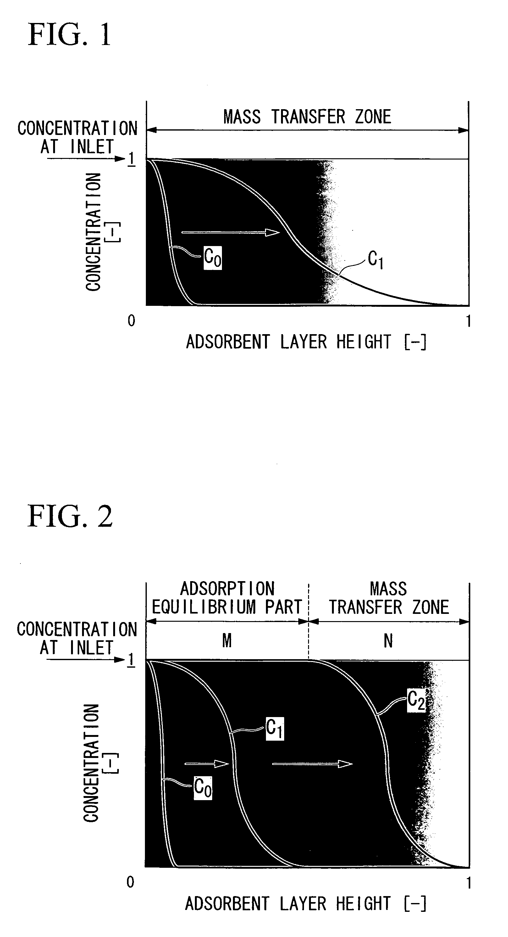
[0058]FIG. 1 schematically represents the concept until a constant pattern of concentration distribution of impurities in the present embodiment is formed. In FIG. 1, the vertical axis represents a relative concentration of carbon dioxide in feed air. Also, the horizontal axis represents the packed height of an adsorbent layer which is normalized to be dimensionless. The point zero on the horizontal axis is the inlet of air, and the point 1 is the outlet of purified air.

[0059]When an adsorption step is started, feed air is fed into an adsorbent layer from the left side of F...

second embodiment

[0090]Next, an embodiment in which carbon monoxide in high purity nitrogen is removed by using, as a gas-purifying agent, a reactant formed of an inorganic porous substance in which nickel metal is supported.

[0091]This reactant is reacted with a trace amount of carbon monoxide and converted into metal carbonyl, and thereby carbon monoxide can be removed. The regeneration of the reactant is performed by allowing it in a heated state and flowing hydrogen so as to reduce it.

[0092]Therefore, at least two purification columns, in which the aforementioned reactant is packed, are provided and operated while alternately switching between a removal step and a regeneration step, and thereby carbon monoxide in high purity nitrogen can be continuously removed.

[0093]In this removal operation, conventionally, purification columns filled with a large amount of reactant are used, and the switching time is set long, such as 2 to 3 days. In this conventional method, a large amount of reactant has to ...

example 1

[0100]Here is a description of the case of purifying air having a feed air pressure: 550 kPa (absolute pressure), an air temperature: 10° C., an air flow rate: 30,000 Nm3 / hour, and a carbon dioxide content: 400 ppm (volume).

[0101]In equation (1), in the case of α=1.04, T=2 hours, u=0.33 m / s, and q=1.33 mol / kg, the result became H≧0.52 m.

[0102]Here, when the first aspect of the present invention was examined, the load of carbon dioxide flowing into an adsorbent layer in the purification step became as follows.

Load=30000 [m3 / hour]×400 [ppm]×10−6×2 [hour]÷0.0224 [Nm3 / mol]=1072 [mol]

Column diameter=(30000 [N m3 / hour]×101 [kPa]÷550 [kPa]×283 [K]÷273 [K]×4÷π÷0.33 [m / s]+3600 [s / hour])0.5=2.47 [m]

[0103]When an adsorbent having a packed density of 650 kg / m3 was used, the adsorption capacity possessed by half of the amount of an adsorbent was as follows.

Adsorption capacity possessed by half of amount of adsorbent=2.472×π÷4×0.52×650×1.33÷2=1077 [mol]

[0104]Accordingly, adsorption capacity posse...


PUM

PropertyMeasurementUnit
Temperatureaaaaaaaaaa
Speedaaaaaaaaaa
Currentaaaaaaaaaa

Abstract

A gas purifier of the present invention includes a purifier in which a gas-purifying agent is packed, wherein a gas is fed into the purifier, and impurities in the gas are removed by a thermal swing adsorption method, in which an amount A of the gas-purifying agent is determined such that an impurities-removing capacity possessed by half of the amount A of the gas-purifying agent is equal to the total amount of impurities in the gas to be purified in one purification step, and the amount of the gas-purifying agent packed in the purifier is the amount A or more.

Description

TECHNICAL FIELD[0001]The present invention relates to a gas purifier which removes impurities contained in a gas such as carbon dioxide contained in air or carbon monoxide contained in high purity nitrogen, and to a method for gas purification using the same. In particular, the present invention relates to a gas purifier and a method for gas purification which are suitable for removing carbon dioxide in feed air in cryogenic air separation. Moreover, the present invention enables a gas purifier to be downsized.[0002]Priority is claimed on Japanese Patent Application No. 2005-185725, filed Jun. 24, 2005, the contents of which are incorporated herein by reference.BACKGROUND ART[0003]In cryogenic air separation, unnecessary components such as moisture, carbon dioxide, a nitrogen oxide, or a hydrocarbon in feed air are previously removed, and then cryogenic air separation is performed. Recently, an adsorption method is used for this removal of unnecessary components.[0004]This adsorptio...

Claims


Application Information

Patent Timeline
IPC IPC(8): B01D53/02
CPCB01D53/04B01D53/0462B01D53/261B01D2253/104B01D2253/108B01D2253/304Y02C10/08B01D2257/502B01D2257/504B01D2257/80B01D2259/40007B01D2259/416B01D2256/10Y02C20/40
Inventor NAKAMURA, MORIMITSUKAWAI, MASATO
Owner TAIYO NIPPON SANSO CORP
Why Eureka
Try Eureka