

Rolling yoke mount for an intra-oral 3D x-ray system
Patent Information
- Authority / Receiving Office
- US · United States
- Patent Type
- Applications(United States)
- Current Assignee / Owner
- SIRONA DENTAL
- Publication Date
- 2016-10-06
Smart Images
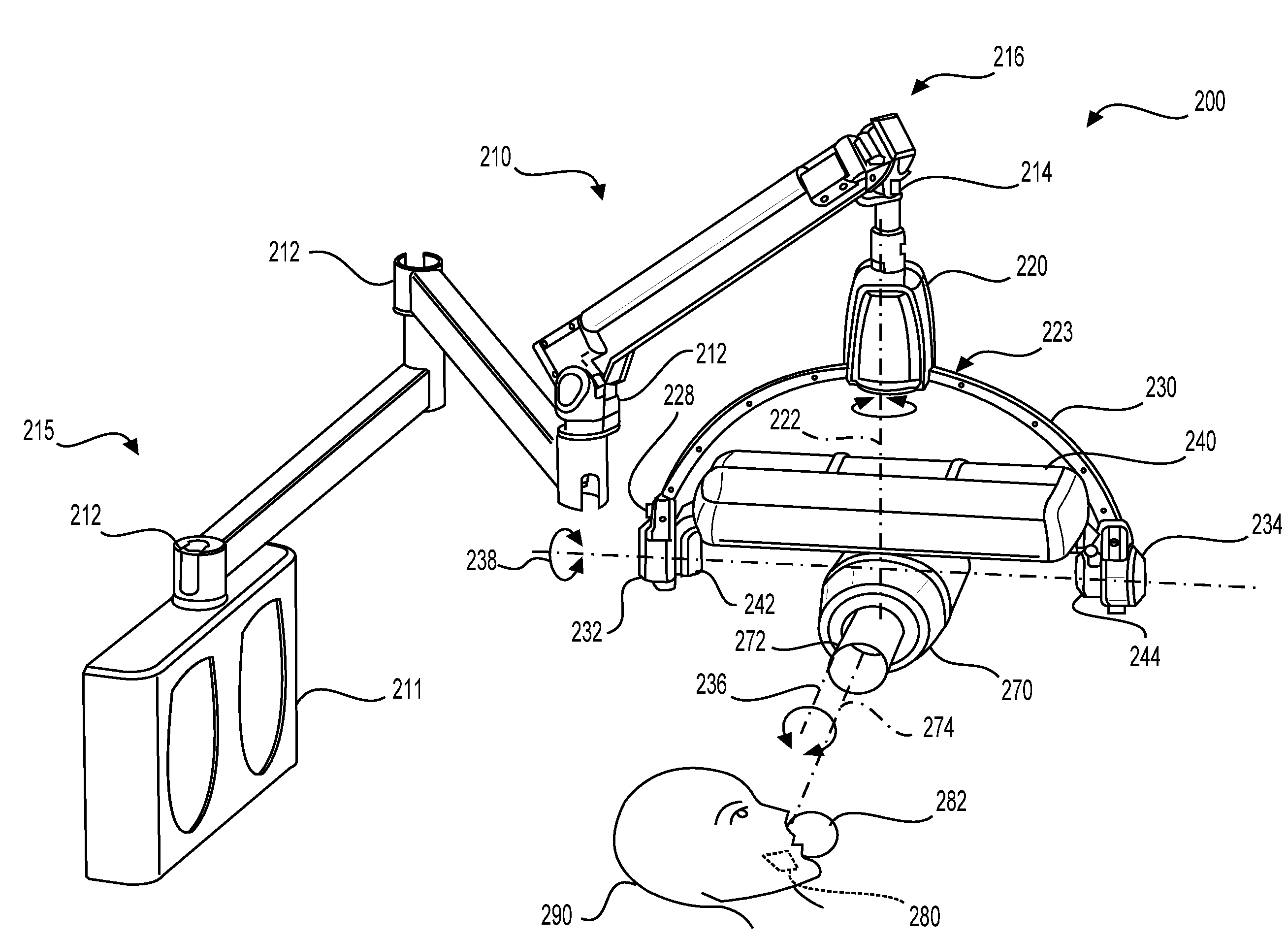
Figure 1 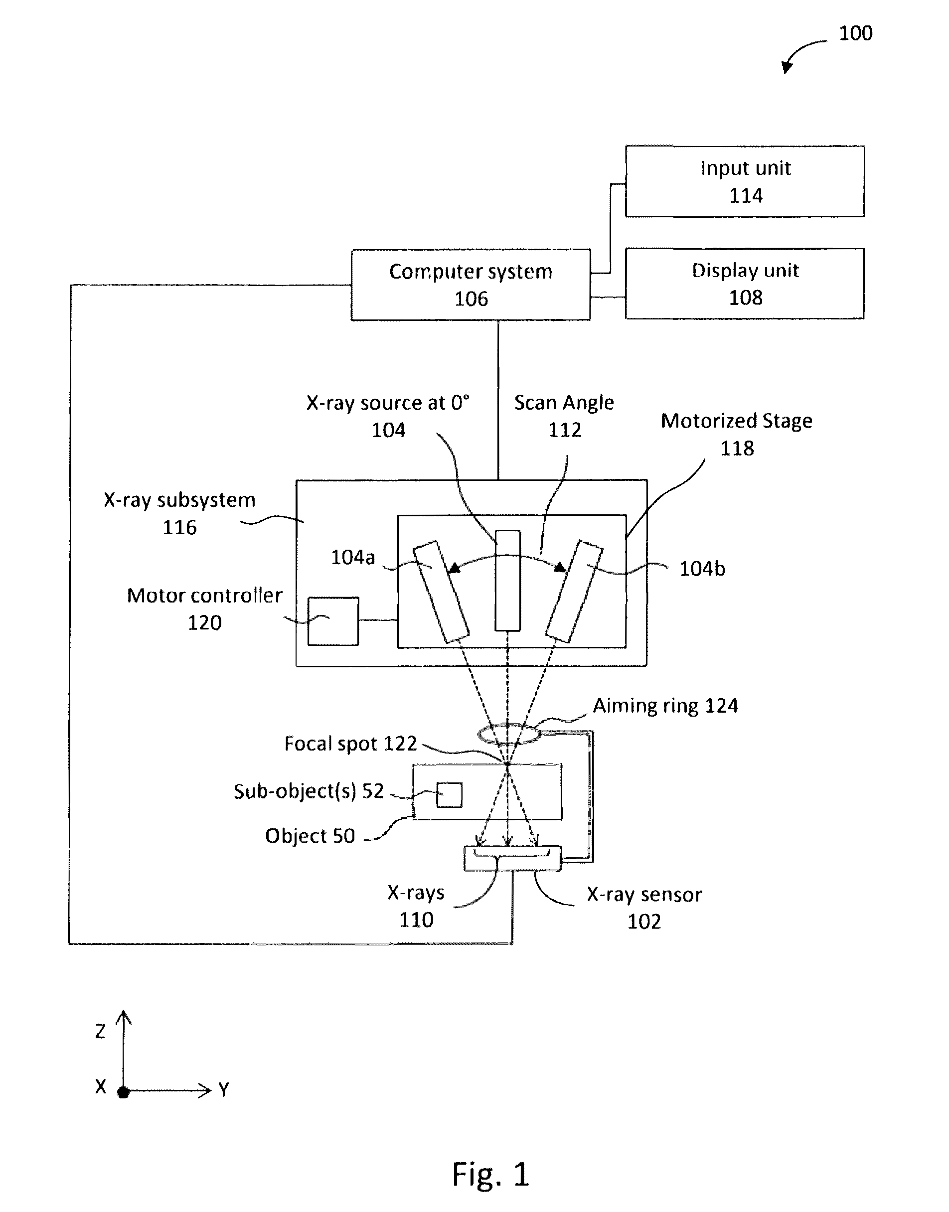
Figure 2 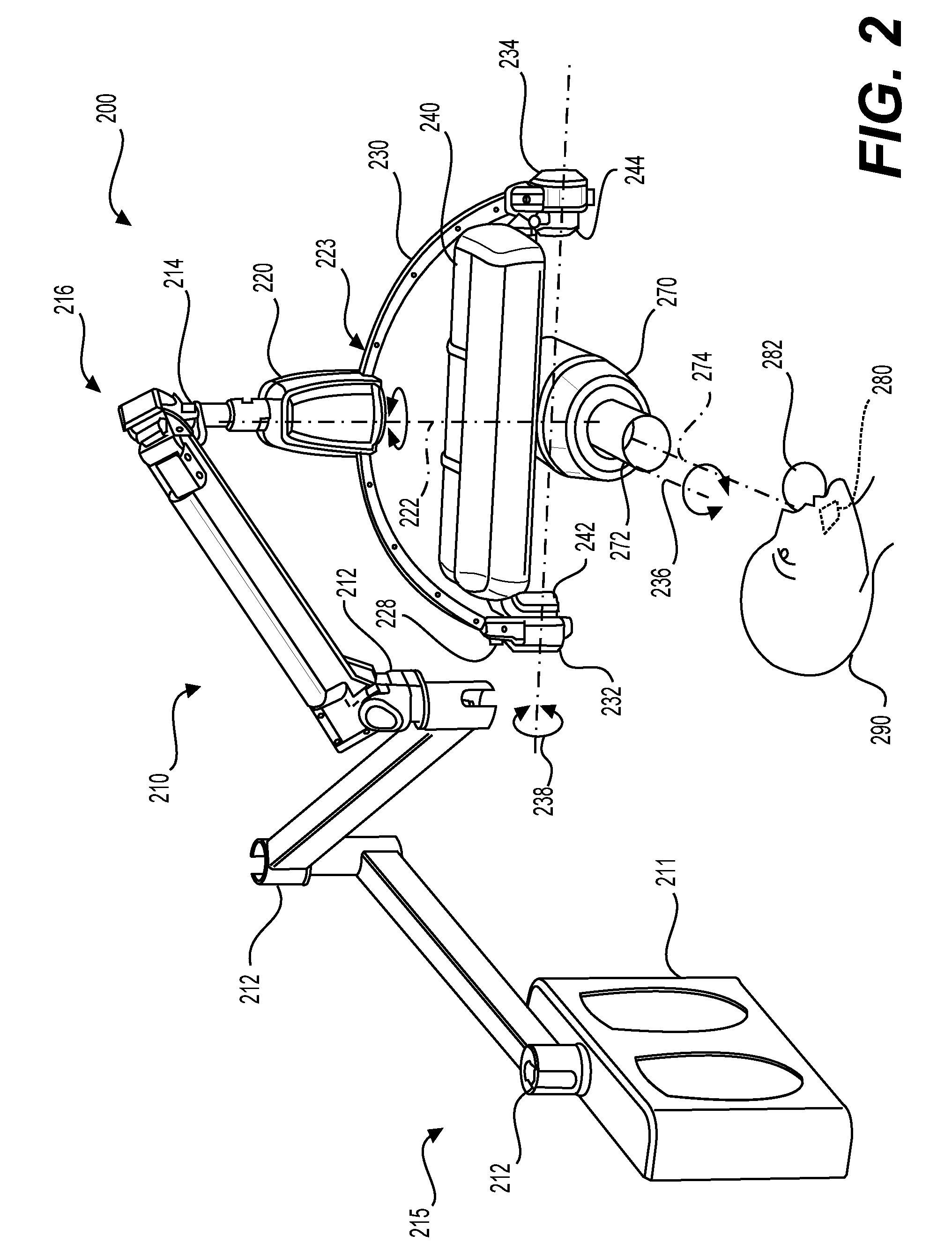
Figure 3
Abstract
Description
BACKGROUND
[0001] 1. Field of the Invention
[0002] The present application relates generally to an x-ray source mounting system, and, more particularly, to an adjustable and ergonomic motorized mounting system for sweeping an x-ray source to acquire an intraoral tomosynthesis dataset.
[0003] 2. Description of Related Art
[0004] X-ray radiography can be performed by positioning an x-ray source on one side of an object (e.g., a patient) and causing the x-ray source to emit x-rays through the object toward an x-ray detector (e.g., radiographic film, a photostimulable phosphor plate, or a digital detector) located on the other side of the object. The x-ray source and detector remain substantially stationary during the radiography procedure. As the x-rays pass through the object, their energies are absorbed to varying degrees depending on the composition of the object, and x-rays arriving at the detector form a two-dimensional (2D) x-ray image (also known as a radiograph) based on the cumulative...