
Device For Creating A Sound Source

a sound source and device technology, applied in the direction of transducer details, reverberation time, instruments, etc., can solve the problems of inability to provide sufficient accurate measurements, inability to achieve measurable strength, and large difference in the structure of dodecahedral loudspeakers, etc., to achieve high sound level, and high degree of omnidirectionality

Active Publication Date: 2016-10-06
RSONANCE BV
View PDF2 Cites 5 Cited by
  • Summary
  • Abstract
  • Description
  • Claims
  • Application Information

AI Technical Summary

Benefits of technology

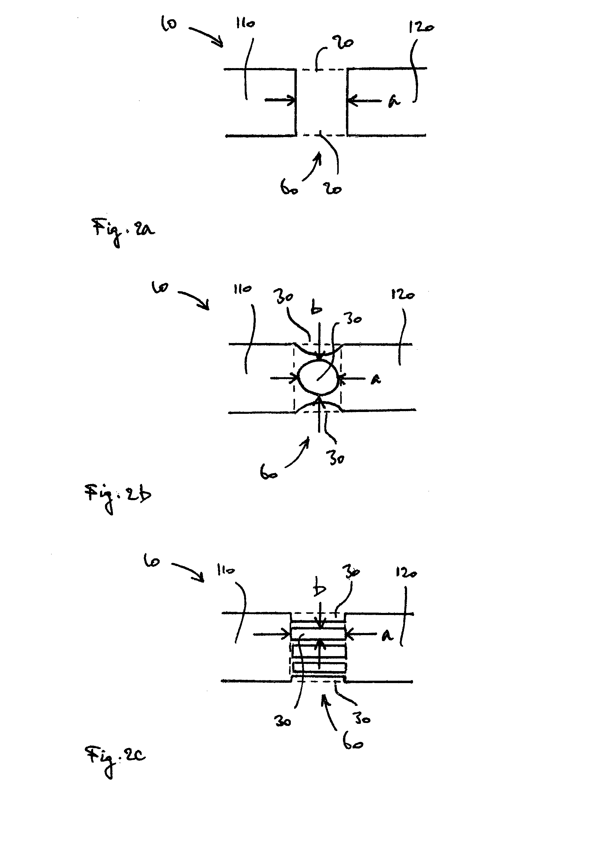
The present invention provides a solution to the problem of lack of omnidirectionality in loudspeakers used in acoustic analyses. This device creates a sound source with measurable strength, providing a relatively high degree of omnidirectionality for a wide range of frequencies and sound levels. The device allows a sound wave to propagate in three dimensions, providing a high degree of omnidirectionality. The size of the sound emission area is important, with smaller sizes providing increased degrees of omnidirectionality. The outer surfaces of the housing are shaped to improve the degree of omnidirectionality. Overall, this device provides a more accurate and complete analysis of sound patterns in a space.

Problems solved by technology

Whereas for a microphone, omnidirectionality is relatively easily achievable by making it smaller, for a loudspeaker, the solution is less simple.
For frequencies higher than a certain limit, a difference of several dB in sound level has been found to exist between various positions at a same radial distance away from the device, which is too large a difference to provide sufficiently accurate measurements.
The dodecahedral loudspeaker furthermore has a relatively complex structure, and is relatively expensive.
Loudspeakers as described are not known to provide a relatively high degree of omnidirectionality in combination with a high output level, or to provide a degree of omnidirectionality that is at least suitable for sufficiently accurate measurements using relatively high frequencies.

Method used


Image

  • Device For Creating A Sound Source
  • Device For Creating A Sound Source
  • Device For Creating A Sound Source

Examples


Embodiment Construction

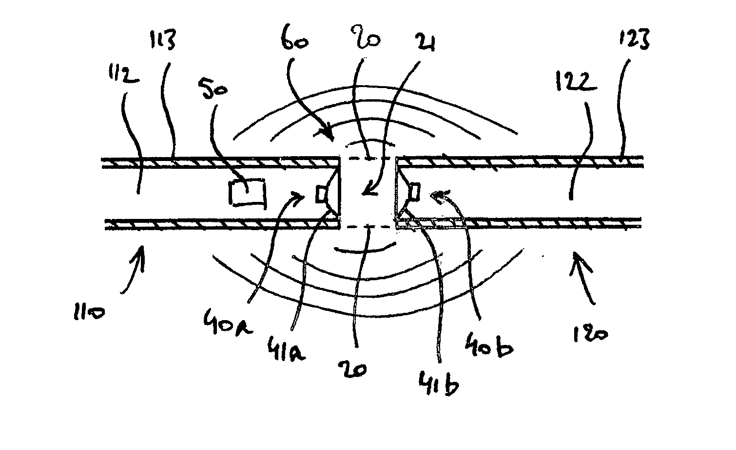
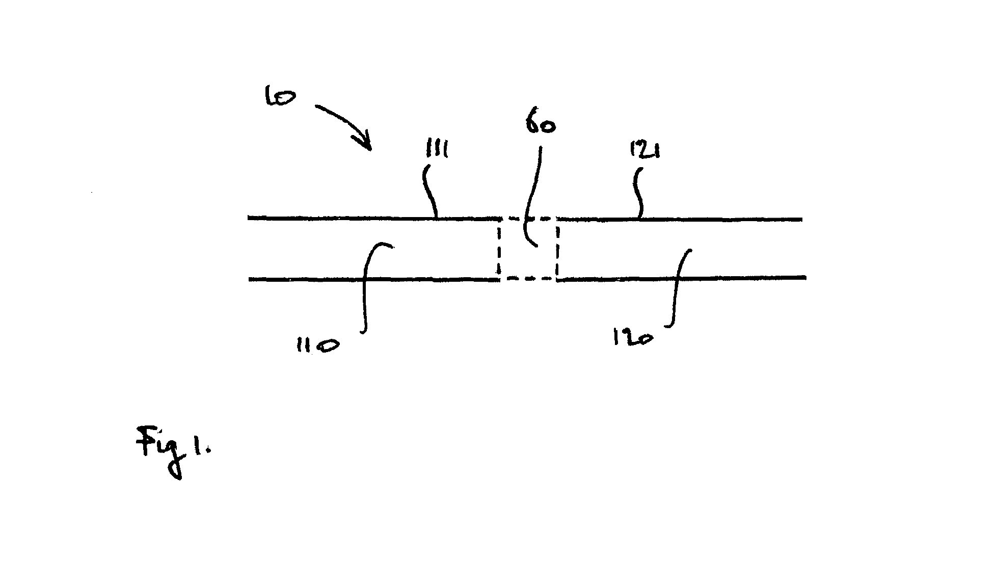
[0041]With reference to FIG. 1, a device according to the invention comprises a housing 10. The housing 10 comprises a first portion 110 and a second portion 120, wherein the two portions 110, 120 are spaced apart along a longitudinal axis of the housing 10 so as for a sound emission area 60 to be formed as an intermediate area in between the first portion 110 and the second portion 120.

[0042]The housing 10 comprises a pair of cylindrical outer surfaces 111, 112 formed as the outer surfaces of the first portion 110 and the second portion 120. By the outer surfaces 111, 121 being cylindrical, the surfaces 111, 121 are meant each to have a continuous circumference lying in a plane perpendicular to the longitudinal axis of the housing 10. Within the scope of the invention, the shape of the circumference may be round, polygonal, for instance hexagonal, or any other shape. Preferably, the shape is rotationally symmetric about the longitudinal axis.

[0043]It is noted, that although FIG. 1 ...


PUM


Abstract

Described is a device for creating a sound source comprising integrated measuring means (50) for measuring a property representative of the strength of the sound source, the device comprising a sound generator (40a, 40b) for generating sound within an annular space defined around a central axis, the device comprising a pair of guiding surfaces (113, 123) for guiding sound away from the annular space in opposite directions along the central axis. With sound being guided as described, sound in addition being allowed to propagate outside the device in a radial direction with respect to the central axis, a high degree of omnidirectionality of the created sound source is attained.

Description

FIELD OF THE INVENTION[0001]The present invention relates to a device for creating a sound source, the device comprising integrated measuring means for measuring a property representative of the strength of the sound source, the device comprising a housing having a sound emission area comprising at least one emission opening for emitting a sound wave, and at least one sound generator for generating a sound wave, arranged in the housing so as for a generated sound wave to radiate from the sound emission area.BACKGROUND OF THE INVENTION[0002]It is known for the acoustics of a certain environment to be analysed using a measuring system comprising a multitude of spatially distributed loudspeakers, wherein a single microphone is positioned at a certain central location.[0003]In an alternative setting, a measuring system for analysing the acoustics of an environment may comprise a multitude spatially distributed microphones, wherein at a central location, a single loudspeaker is positione...

Claims


Application Information

Patent Timeline
IPC IPC(8): H04R1/32G01H7/00H04R29/00
CPCH04R1/323G01H7/00H04R29/001G10K9/13G10K9/22
Inventor VAN DER LINDEN, PETRUS JOHANNES GERARDUS
Owner RSONANCE BV
Learn More