End effector, robot, and rotary milking system

Inactive Publication Date: 2016-10-13
DELAVAL HLDG AB
View PDF6 Cites 9 Cited by
  • Summary
  • Abstract
  • Description
  • Claims
  • Application Information

AI Technical Summary

Benefits of technology

[0005]It is therefore an aim to provide an end effector, which can withstand mechanical forces to an outer end portion thereof without the risk of damaging the end

Problems solved by technology

As a result, the end effector has to withstand not only dirt, animal faeces, various fluids, and possibly chemicals, such as cleaning chemicals, but also kicks from the milking animals and other mechanical stresses and strains Typically, such exposure to mechanical forces may lead to damages of the end effector, of the camera, or of the robot used.
The camera ma

Method used


Image

  • End effector, robot, and rotary milking system
  • End effector, robot, and rotary milking system
  • End effector, robot, and rotary milking system

Examples


Example

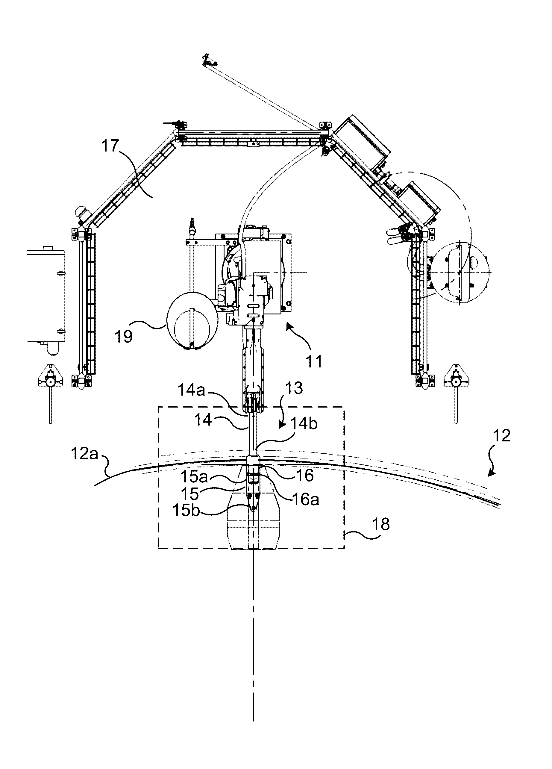
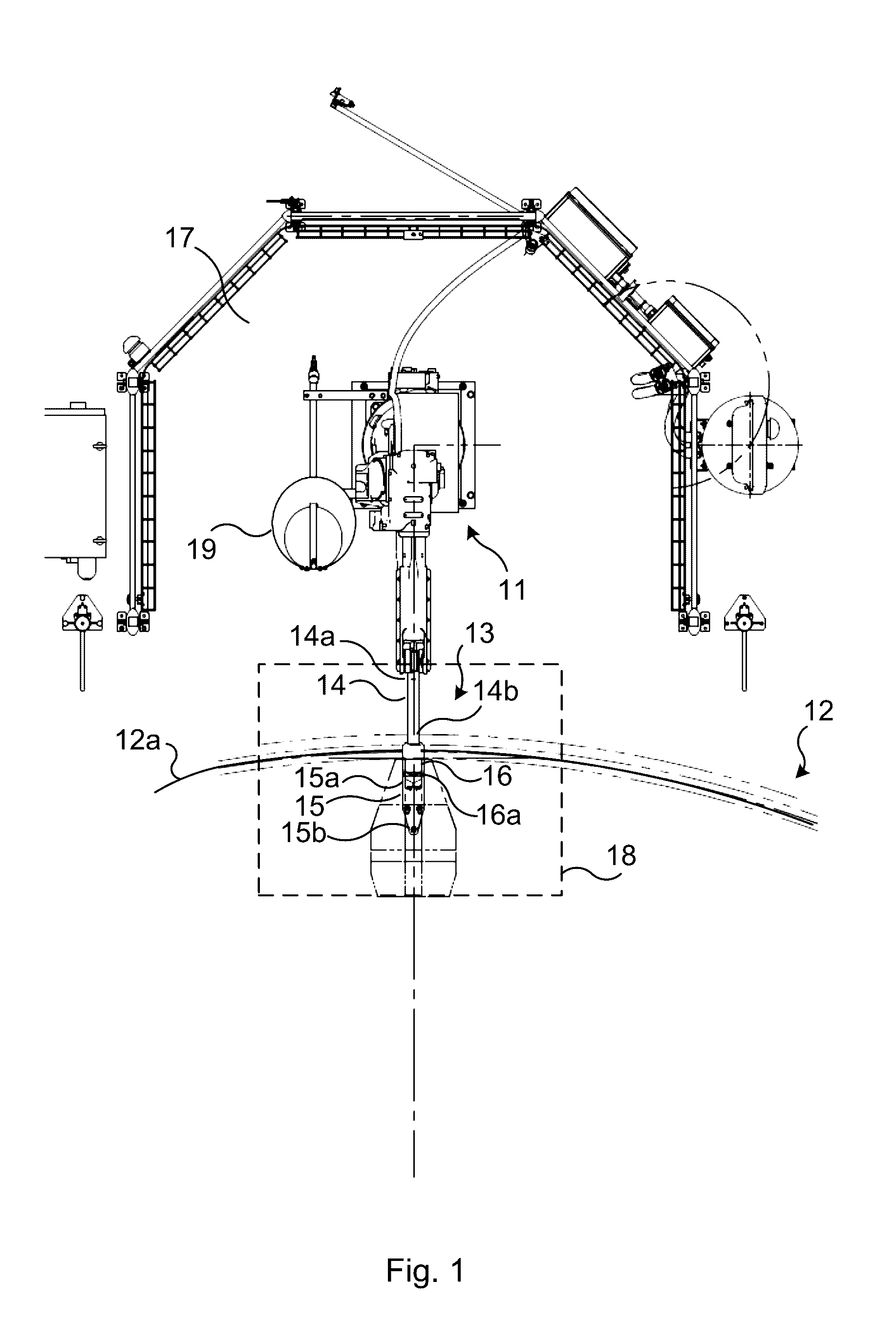
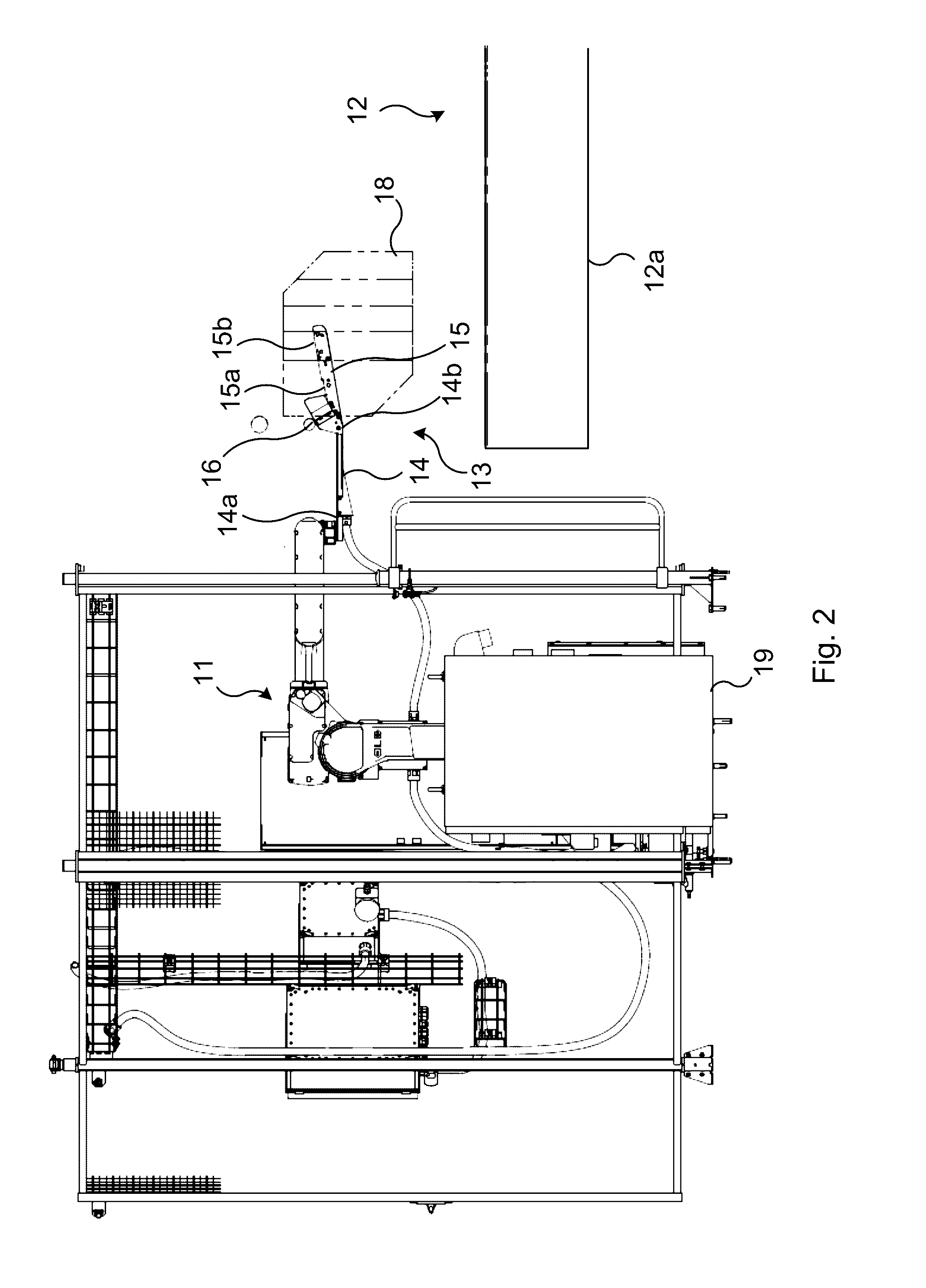
[0055]FIGS. 1-2 illustrate, schematically, in top and side views portions of a rotary milking system 12 equipped with a robot 11 according to one embodiment.

[0056]The rotary milking system 12 comprises a rotating platform 12a, on which the milking animals are standing while they are milked. The robot 11 is equipped with an end effector 13 comprising an inner arm section 14 and an outer arm section 15, and a camera 16 with a front window 16a. The inner arm section 14 comprises an inner end portion 14a and an outer end portion 14b and the outer arm section 15 comprises an inner end portion 15a and an outer end portion 15b, wherein the inner end portion 14a of the inner arm section 14 is mounted to the robot 11 and the inner end portion 15a of the outer arm section 15 is rigidly connected to outer end portion 14b of the inner arm section 14. Thus, the end effector 13 has the shape of an elongated straight or slightly angled arm mounted to the robot 11.

[0057]The camera 16 is mounted on ...


PUM


Abstract

An end effector that mounts to a robot and discharges animal treating fluid onto the teats of a milking animal includes a rigid inner arm section and a flexible outer arm section, and a camera with a front window. An inner end portion of the inner arm section is mountable to the robot, the inner end portion of the outer arm section is rigidly connected to outer end portion of the inner arm section, the camera is mounted on an upper side of the inner arm section with the front window facing the outer arm section, and the outer arm section is provided with at least one nozzle in the outer end portion, the nozzle being directed upwards such that animal treating fluid can be discharged through the nozzle and upwards towards a teat of a milking animal during use of the robot.

Description

TECHNICAL FIELD OF THE INVENTION[0001]The present invention relates generally to robot based discharging of fluid onto the teats of a milking animal, e.g. subsequent or prior to milking.DESCRIPTION OF RELATED ART AND BACKGROUND OF THE INVENTION[0002]Milking systems with robots configured to discharge a post-milking treatment fluid onto the teats of milking animals after that the milking animals have been milked are known. Likewise, milking systems with robots configured to discharge a pre-milking treatment fluid onto the teats of milking animals before the milking animals have been milked are known.[0003]Such robots comprises typically an end effector mounted to the robot and a camera mounted on the end effector, wherein nozzles, through which a treatment fluid can be discharged onto the teats of milking animals, are arranged in an outer end portion of the end effector. It shall be appreciated that the end effector, and particularly the outer end portion thereof, is operated in a ha...

Claims


Application Information

Patent Timeline
IPC IPC(8): A01J7/04A01J5/007H04N5/232B25J11/00G06T1/00A01J5/017A01J7/02
CPCA01J7/04A01J5/0175A01J5/007H04N5/23229B25J11/008G06T1/0014A01J7/025A01J5/017A01K1/126B25J11/00H04N23/80
Inventor AXELSSON, THOMASERIKSSON, PETERNIEMELA, TAPANI
Owner DELAVAL HLDG AB
Why Eureka
Try Eureka