Energy storage system

Inactive Publication Date: 2016-10-20
ROBERT BOSCH GMBH
View PDF3 Cites 2 Cited by
  • Summary
  • Abstract
  • Description
  • Claims
  • Application Information

AI Technical Summary

Benefits of technology

[0016]It is particularly preferred that the maximum capacity is at least 10% greater than the nominal capacity. Depending on the type and maximum capacity of the electrical energy store, 90% of the maximum capacity may be achieved, for example, after approximately 50% to 70% of the charging time if the CCCV process is used. By—largely—dispensing with the constant voltage process, a substantial saving of charging time may therefore be ach

Problems solved by technology

The termination of the charging process at the end of charging ensures that the elec

Method used


Image

  • Energy storage system
  • Energy storage system
  • Energy storage system

Examples


Example

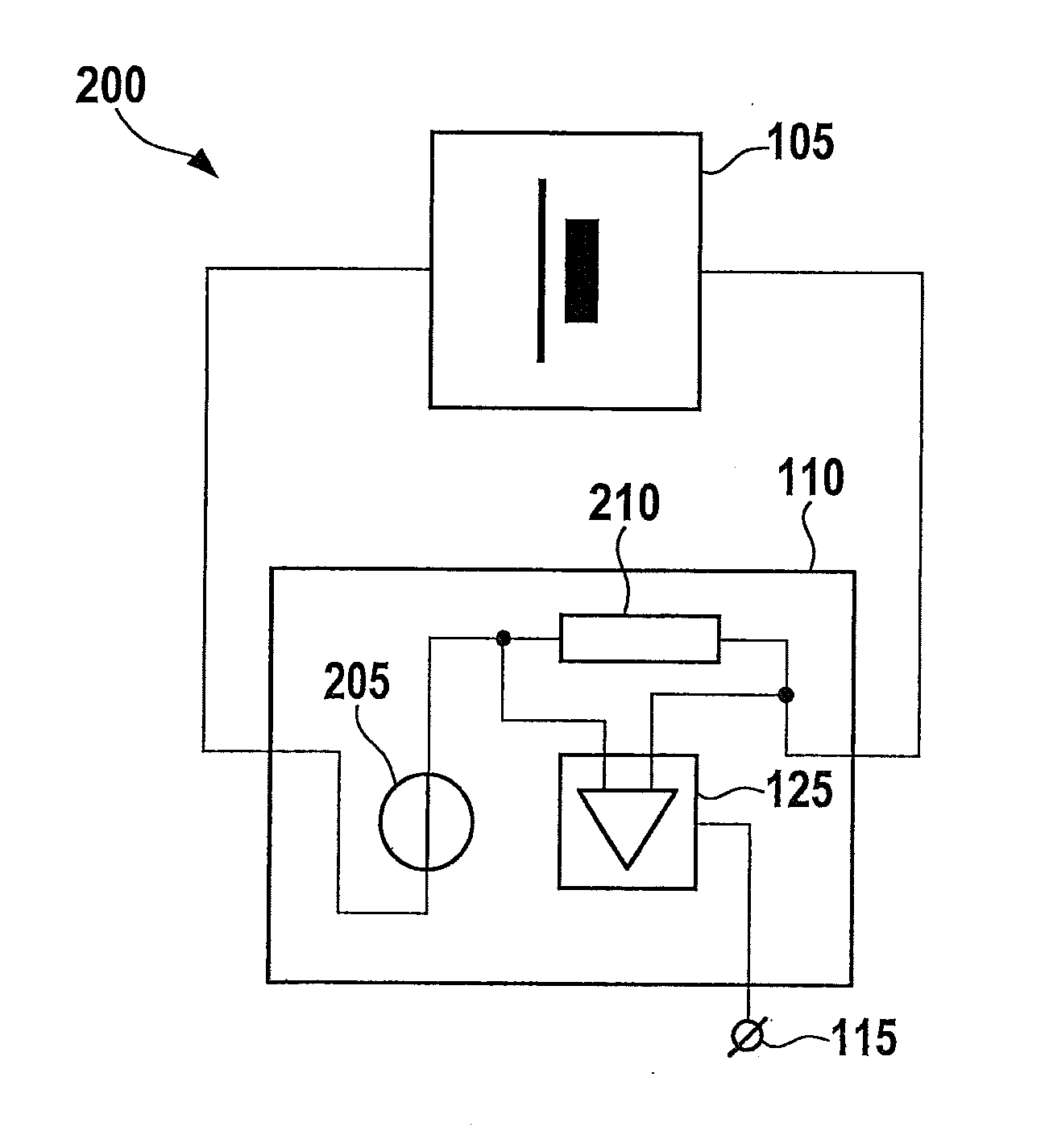
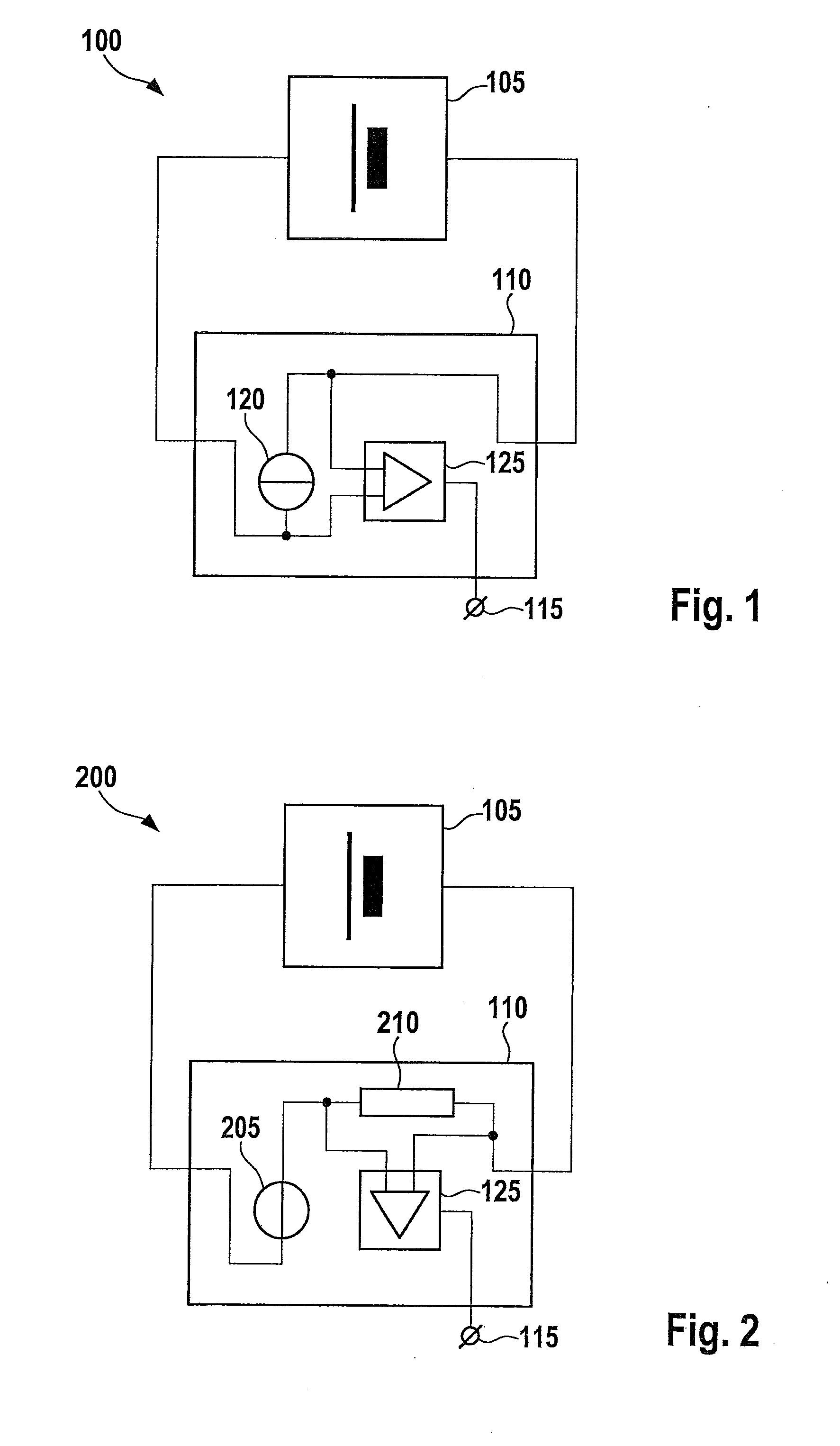
[0023]FIG. 1 shows a system 100 including an electrical energy store 105 and a charging unit 110. Energy store 105 may be separable from charging unit 110 or integrated into it. Energy store 105 preferably includes multiple identical cells of a conventional storage battery technology, such as lithium-ion or metal-hydride technology, for example. Energy stores 105 of this type are available under the name, “Akkupack.” The internal configuration of energy store 105 is not further discussed here.

[0024]Charging unit 110 may generally be connected to an external energy source which is not illustrated here. This energy source may be, for example, a power network or an electrical system of a motor vehicle. Charging unit 110 is configured to charge electrical energy store 105 up to a nominal capacity which is significantly less than a maximum capacity of energy store 105. The maximum capacity thereby indicates how much electrical energy may be made available in energy store 105 without subs...


PUM


Abstract

A system includes a rechargeable electrical energy store having a predetermined nominal capacity and a predetermined maximum capacity, the maximum capacity being higher than the nominal capacity, and a charging unit for controlling a charging process of the energy store. The charging unit is configured for the purpose of charging the energy store until the amount of energy stored in it equals the nominal capacity, and then to determine an end of charging.

Description

CROSS REFERENCE[0001]The present application claims the benefit under 35 U.S.C. §119 of German Patent Application No. 102015206871.4 filed on Apr. 16, 2015, which is expressly incorporated herein by reference in its entirety.FIELD[0002]The present invention relates to an energy storage system. In particular, the present invention relates to a system which includes a rechargeable electrical energy store and a charging unit for the energy store.BACKGROUND INFORMATION[0003]An electric hand tool such as a cordless screwdriver, for example, a flashlight or an electric edge trimmer, obtains the electrical energy required for its operation from a rechargeable electrical energy store. The energy store may be in the form of a rechargeable battery pack, for example, and may be removed from the device when an electrical energy store is exhausted to make uninterrupted work possible. The discharged electrical energy store may then be recharged at a charging unit. The charging may also take place...

Claims


Application Information

Patent Timeline
IPC IPC(8): H02J7/00
CPCH02J7/0029H02J2007/0037H02J7/0057H02J7/0086H01M10/44H01M10/46H02J7/0069H02J7/00302H02J7/00712Y02E60/10
Inventor SORHAGE, CONSTANZE
Owner ROBERT BOSCH GMBH
Why Eureka
Try Eureka