
Contactless multi-charger system and controlling method thereof

A wireless charger, multi-charger technology, applied in electromagnetic wave systems, current collectors, circuit monitoring/indication, etc., can solve the problems of increasing primary coil power, difficulty in other applications, damage to wireless chargers, etc., to save total charging time, improve charging efficiency, prevent damage

Active Publication Date: 2012-05-30
INTEL CORP
View PDF0 Cites 6 Cited by
  • Summary
  • Abstract
  • Description
  • Claims
  • Application Information

AI Technical Summary

Problems solved by technology

[0005] However, these conventional wireless chargers are not practical since they can only supply power to portable terminal modules, and they are also difficult to use for other applications
[0006] Also, the wireless charger may be damaged due to the fact that when metal is placed near the magnetic field generated by the primary coil, the magnetic field changes thereby increasing the loss of electrical energy (power, or power) in the primary coil

Method used


Image

  • Contactless multi-charger system and controlling method thereof
  • Contactless multi-charger system and controlling method thereof
  • Contactless multi-charger system and controlling method thereof

Examples


Embodiment Construction

[0048] Hereinafter, preferred embodiments of the present invention will be described in detail with reference to the accompanying drawings.

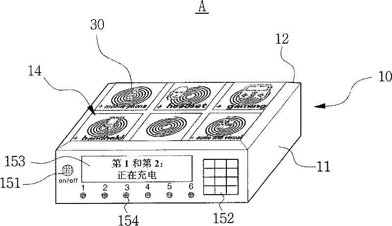
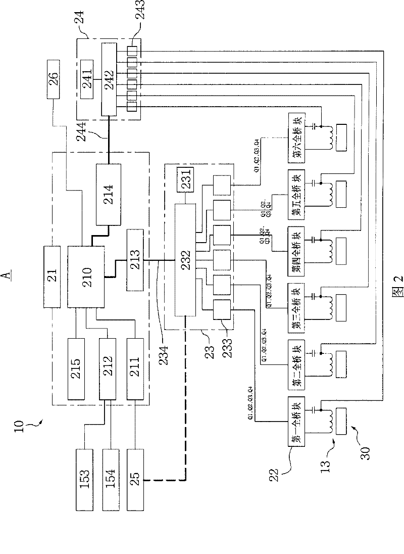
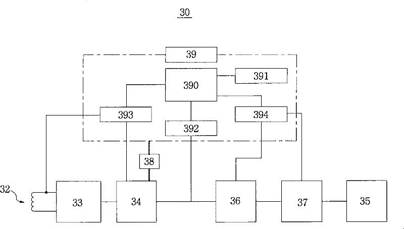
[0049] figure 1 is a perspective view showing the wireless multi-power transmission device of the wireless multi-charger system according to the present invention, figure 2 is a control block diagram representing the wireless multi-power transmission device of the wireless multi-charger system according to the present invention, image 3 is a block diagram representing a wireless multi-power transmission device of a wireless multi-charger system according to the present invention, Figure 4 is a control flow diagram representing the wireless multi-power transmission device of the wireless multi-charger system according to the present invention, Figure 5 is a control flow diagram representing the wireless multi-power transmission device of the wireless multi-charger system according to the present invention, and Image 6 is a control...


PUM


Abstract

The invention discloses a wireless multi-charger system capable of saving the total charging time of a large number of wireless power transmission devices since one wireless multi-power transmission device includes a plurality of the wireless power transmission devices so that a large number of the wireless power transmission devices can be charged with electricity, and preventing the damage of the wireless power transmission devices and the wireless multi-power transmission device although foreign substances are put on charger blocks that are not charged. The wireless multi-charger system (A) according to the present invention includes an external body formed as a wireless charger case (11), wherein the wireless charger case has a wireless charger table (12) formed in an upper surface thereof, wherein the wireless charger table has a plurality of charger blocks (14), each of which includes a primary charging core (13), wherein the full-bridge resonant converter is present in a pluralform and coupled respectively to a plurality of the charger blocks, wherein a multi-gate driver module is provided to transmit a converted power signal to each of a plurality of the full-bridge resonant converters under the control of the central controller, and wherein a reception signal processor module is coupled to a plurality of the charger blocks for processing a signal transmitted from thewireless power transmission device (30) and supplies the processed signal to the central controller.

Description

technical field [0001] The present invention relates in particular to a wireless charger system, and more particularly to a wireless multi-charger system capable of saving the total charging time of a large number of wireless power transmission devices. Charge a plurality of wireless power transmission devices and prevent damage to the wireless power transmission device and the wireless multi-power transmission device even when there is a foreign object on a charger block that is not being charged. Background technique [0002] Generally, since the user uses the portable wireless power transmission device while moving, the common portable wireless power transmission device, such as a mobile phone, PDA, PMP, DMB terminal, MP3 or notebook computer, does not provide a traditional household power supply. Therefore, there is a need to install removable batteries or rechargeable batteries in portable wireless power transfer devices. [0003] However, as a charger for charging the...

Claims


Application Information

Patent Timeline
Patent Type & Authority Patents(China)
IPC IPC(8): H02J7/00H02J17/00H01M10/44H02H7/18
CPCY02E60/12Y02B70/1433Y02E60/10H01M10/4257H02J7/0044H02J7/0047H02J50/12H02J50/40H02J50/60H02J50/80H02J50/90
Inventor 郑春吉
Owner INTEL CORP
Learn More