
Method and apparatus for handover in a wireless communication system

a wireless communication system and wireless communication technology, applied in the direction of electrical equipment, wireless communication, synchronisation arrangement, etc., can solve the problems of call interruption, packets may be too late, and the rach procedure will take several attempts, so as to eliminate or minimize the interruption time, the effect of avoiding contention

Active Publication Date: 2016-10-20
GOOGLE TECHNOLOGY HOLDINGS LLC
View PDF2 Cites 6 Cited by
  • Summary
  • Abstract
  • Description
  • Claims
  • Application Information

AI Technical Summary

Benefits of technology

This approach reduces handover interruption time, simplifies the handover process, and minimizes contention issues, ensuring effective and efficient handover operations with reduced complexity in wireless communication systems.

Problems solved by technology

Unfortunately, signaling in current networks result in call interruptions when the mobile station is handed over from one base station to another.
Due to delays involved in re-routing un-transmitted packets for transmission via the target base station, such packets may be too late and may simply be discarded, especially for real-time services such as voice.
Furthermore, the probability of success of a Random Access Channel (RACH) attempt can vary and, in cases where the mobile station is near a boundary of the source base station and the target base station, it is likely that the RACH procedure will take several attempts.
Another problem exists for non-contention preambles that are used to avoid RACH transmission conflicts between different mobile stations by distinguishing between different mobile stations.
Assigning a non-contention preamble is a very complex task at the target base station.
While this implementation is necessary to maintain the contention-free property, the likelihood of two or more mobile stations attempting to handover to a target base station at the same RACH opportunity is generally low.

Method used


Image

  • Method and apparatus for handover in a wireless communication system
  • Method and apparatus for handover in a wireless communication system
  • Method and apparatus for handover in a wireless communication system

Examples


Embodiment Construction

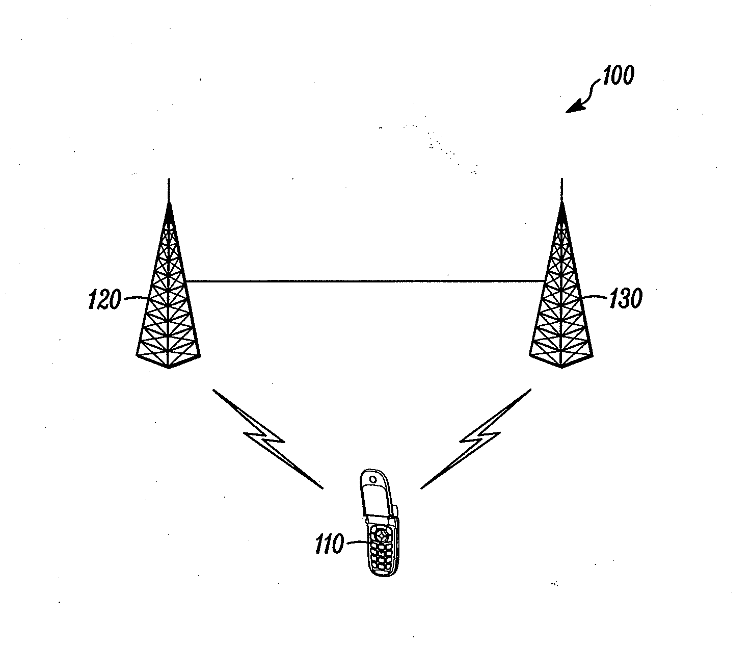
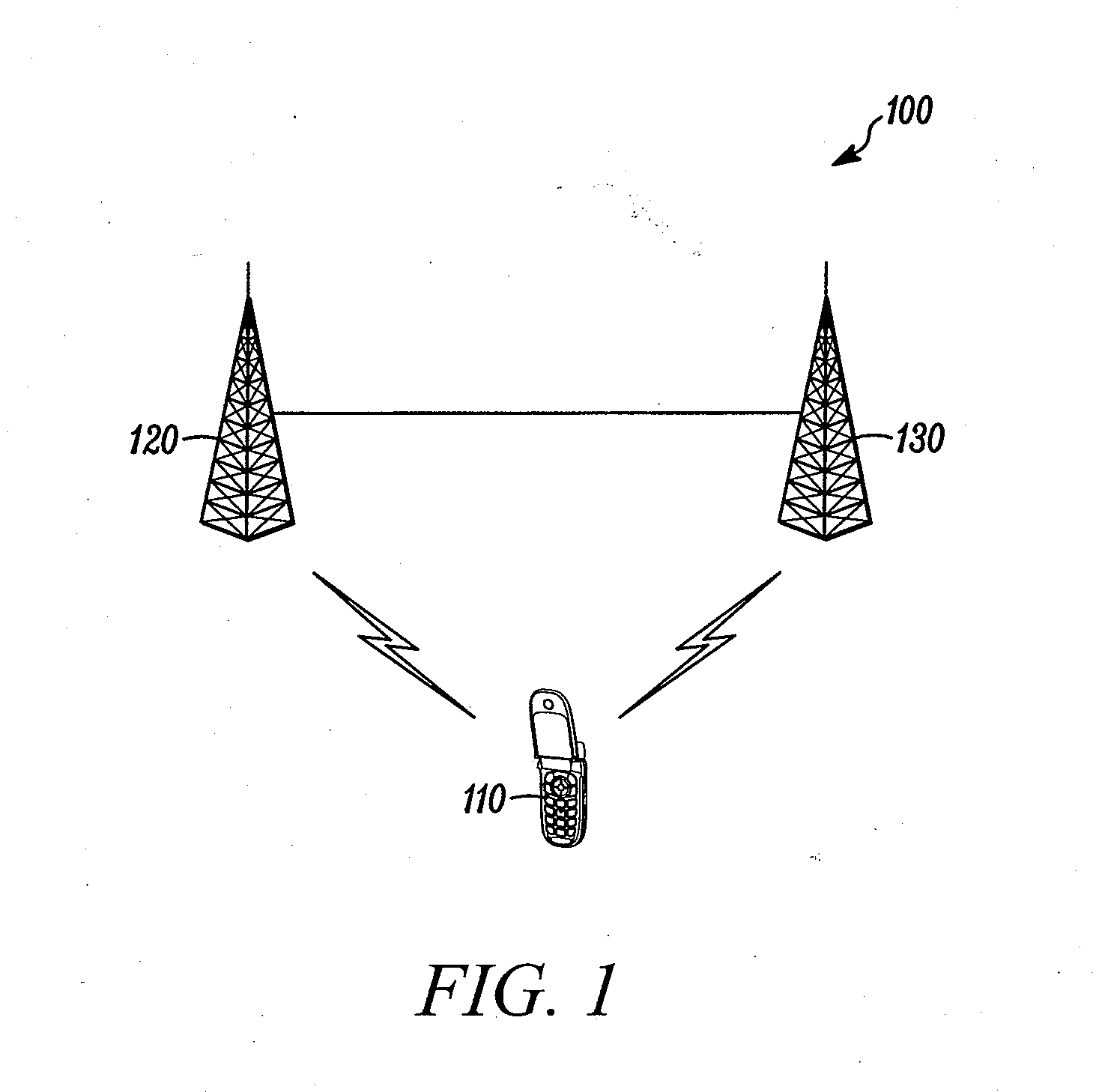
[0017]FIG. 1 is an exemplary diagram of a system 100 according to one embodiment. The system 100 can include a mobile station 110, a source base station 120, and a target base station 130. The mobile station 110 may be a wireless communication device, such as a wireless telephone, a cellular telephone, a personal digital assistant, a pager, a personal computer, a selective call receiver, or any other device that is capable of sending and receiving communication signals on a network including wireless network. The base stations 120 and 130 may be any combination of wireless base stations, cellular base stations, access points, or any other base station useful for sending and receiving wireless signals to and from a mobile station. The system 100 may include any type of network that is capable of sending and receiving signals, such as wireless signals. For example, the system 100 may include a wireless telecommunications network, a cellular telephone network, a Time Division Multiple ...


PUM


Abstract

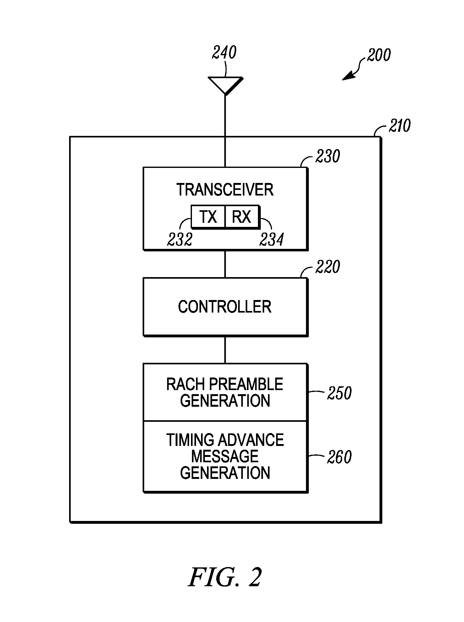
A method and apparatus for handover in a wireless communication system. A handover indication can be received from a source base station (120) that is connected with a mobile station (110). The handover indication can include a random access channel preamble. The random access channel preamble can include a temporary mobile equipment identifier. The random access channel preamble can be received from the mobile station. A timing advance message can be sent in response to receiving random access channel preamble. The timing advance message can be addressed by the random access channel preamble and a source base station identifier. The connection with the mobile station can be switched from the source base station to a target base station (130).

Description

CROSS-REFERENCE TO RELATED APPLICATIONS[0001]This application is a continuation of U.S. patent application Ser. No. 11 / 742,134, filed Apr. 30, 2007, having inventors Muralia Narasimha et al., entitled “Method and Apparatus for Handover in a Wireless Communication System” which is related to the application entitled “Method and Apparatus for Handover in a Wireless Communication System,” Motorola case number CS33279 and the application entitled “Method and Apparatus for Handover in a Wireless Communication System,” Motorola case number CS33396, filed on even date herewith and commonly assigned to the assignee of the present application, which is hereby incorporated by reference.BACKGROUND[0002]1. Field[0003]The present disclosure is directed to a method and apparatus for handover in a wireless communication system. More particularly, the present disclosure is directed to handover of a mobile station from a source base station to a target base station.[0004]2. Description of Related Ar...

Claims


Application Information

Patent Timeline
Patent Type & Authority Applications(United States)
IPC IPC(8): H04W36/00H04W56/00H04W74/08H04W36/08
CPCH04W36/0016H04W36/0072H04W56/001H04W36/0077H04W74/0833H04W56/00H04W74/0838
Inventor NARASIMHA, MURALIKUCHIBHOTLA, RAVI
Owner GOOGLE TECHNOLOGY HOLDINGS LLC
Learn More