
Steering Wheel

Active Publication Date: 2016-10-27
AUTOLIV DEV AB
View PDF1 Cites 15 Cited by
  • Summary
  • Abstract
  • Description
  • Claims
  • Application Information

AI Technical Summary

Benefits of technology

[0010]According to the present invention as described above, the steering wheel is structured such that the heater element is disposed in the vicinity of the cored bar of the grip portion through intermediation of the flexible porous material layer. Consequently, the heater element can be disposed at a distance from the cored bar by the thickness of the porous material layer, and the heater element is disposed at a position close to the surface of the steering wheel, thus improving temperature adjustment efficiency. Employing the flexible porous material layer enables the porous material layer to be easily mounted around the cored bar and also enables a satisfactory feeling of grip to be maintained even when the outer side of the steering wheel is enclosed by the synthetic resin layer. For example, a structure in which a heater element is placed on a frame structure unlike the porous material layer of the present invention may cause the driver to feel uncomfortable to grip the steering wheel even when the surface of the rim is covered by urethane or any other material. Further, in the present invention, gaps of the porous material layer are filled with the synthetic resin, and hence the porous material layer and the heater element can be tightly fixed to the cored bar with reliability. As described above, the structural features of the present invention enable the steering wheel with the temperature adjustment function, which may have a complicated structure in accordance with the prior art, to be manufactured at low cost.
[0011]It is preferred that the heater element in

Problems solved by technology

For example, a structure in which a heater element is placed on a frame structure unlike the porous material layer of the present invention may

Method used


Image

  • Steering Wheel
  • Steering Wheel
  • Steering Wheel

Examples


Example

BACKGROUND

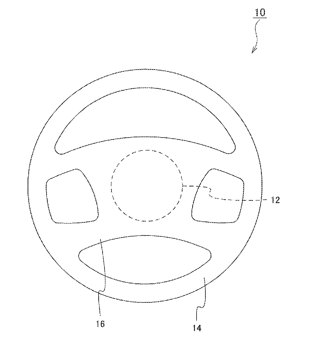
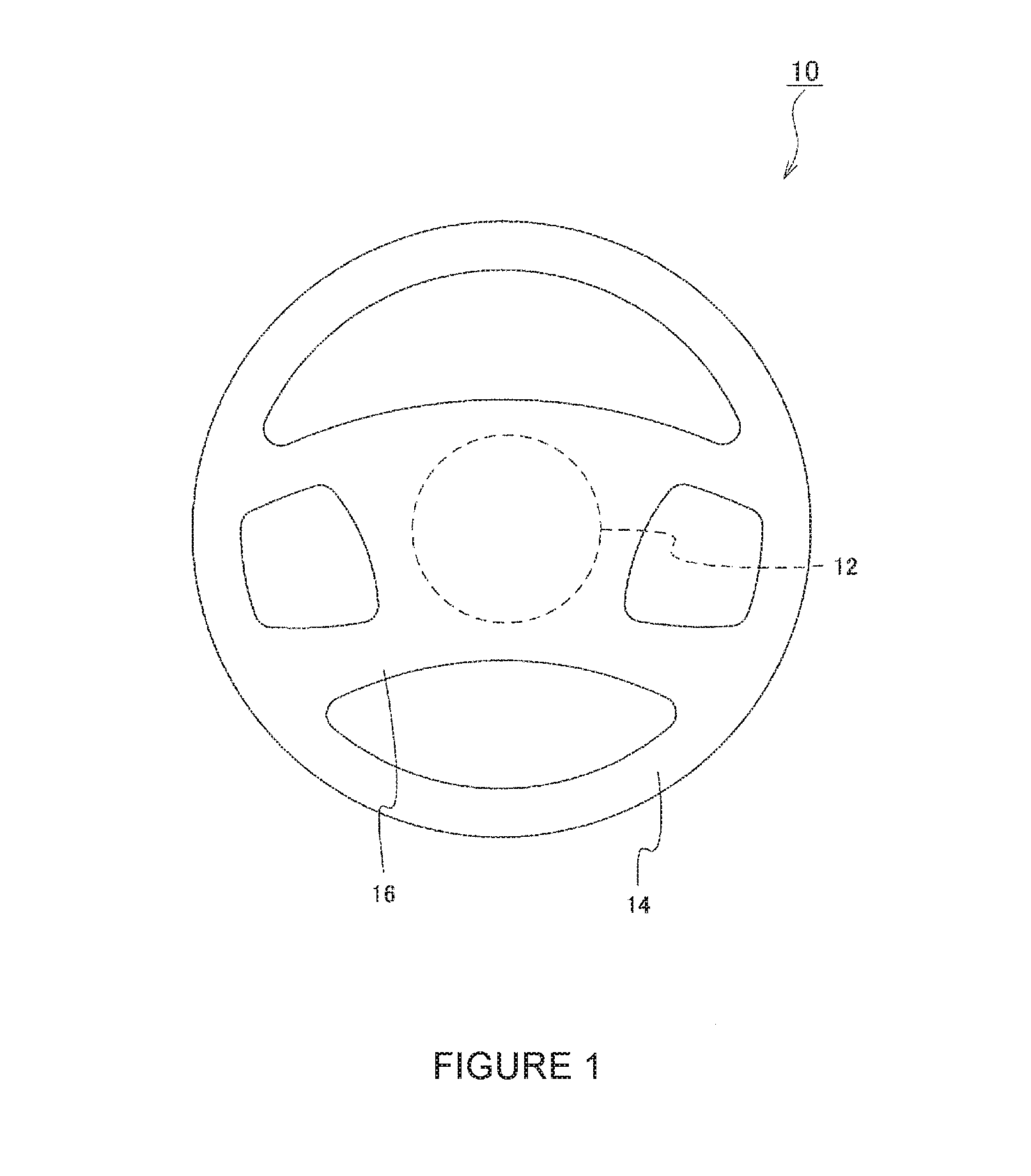
[0020]As illustrated in FIG. 1, the steering wheel 10 according to the present invention includes: a boss portion 12 to be connected to a steering column (not shown); the grip portion 14 to be gripped by a driver; and a spoke portion 16, which connects the boss portion 12 and the grip portion 14 to each other. The grip portion 14 corresponds to a portion generally called “rim”, and can be said to be a portion to be touched by the driver in terms of a temperature adjustment function.

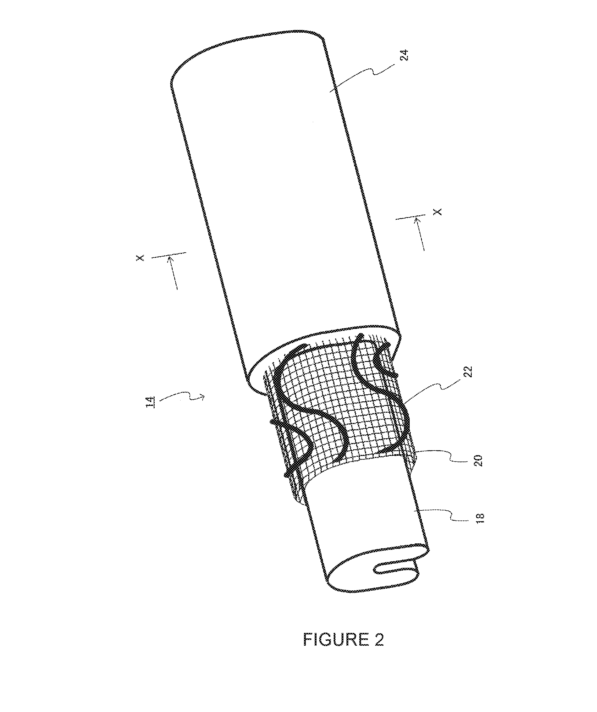
[0021]As illustrated in FIG. 2 and FIG. 3, the grip portion 14 includes: a synthetic resin layer 24 molded by a synthetic resin such as urethane foam; a cored bar 18; a flexible porous material layer 20 disposed on an outer peripheral surface side of the cored bar 18; and a heater element 22 disposed on an outer surface of the porous material layer 20. The porous material layer 20 and the heater element 22 are covered by the synthetic resin layer 24. Then, the synthetic resin layer 24 enters air...


PUM

PropertyMeasurementUnit
Structureaaaaaaaaaa

Abstract

A steering wheel providing minimal cost increase due to addition of a temperature adjustment function. The steering wheel, includes: a boss portion to be connected to a steering column; a grip portion to be gripped by a driver; and a spoke portion, which connects the boss portion and the grip portion to each other. The grip portion includes: a synthetic resin layer molded by a synthetic resin; a cored bar; a flexible porous material layer disposed on an outer peripheral surface side of the cored bar; and a heater element disposed on an outer surface of the porous material layer. The porous material layer and the heater element are covered by the synthetic resin layer.

Description

CROSS REFERENCE TO RELATED APPLICATIONS[0001]This application claims priority to Japanese Application No. 2013-270449, filed on Dec. 26, 2013 and PCT / JP2014 / 077510, filed on Oct. 16, 2014.FIELD OF THE INVENTION[0002]The present invention relates to a structure of a steering wheel having a temperature adjustment function (heater and / or cooler function).BACKGROUND OF THE INVENTION[0003]In recent years, steering wheels having a temperature adjustment function (heater and / or cooler function) have been proposed and put into practical use for automobiles and any other vehicles. For example, a structure in which a heater element is disposed on the outer side of a cored bar has been proposed. Examples of conventional steering wheels with a heater function include a steering wheel disclosed in Japanese Patent Application Laid-open No. 2007-153026.[0004]For a steering wheel having a heater function, it is important to efficiently transfer heat to a steering outer cover. As disclosed in Japane...

Claims


Application Information

Patent Timeline
IPC IPC(8): B62D1/06B29C63/00H05B3/48
CPCB62D1/06H05B3/48B29C63/0073B29K2023/06B29K2075/00B29K2105/04B29L2031/3047H05B2203/017B62D1/065
Inventor KATO, YOUSUKEKIM, JINKEUN
Owner AUTOLIV DEV AB
Learn More