Central air-conditioning system and control method thereof

Active Publication Date: 2015-04-02
TAN ZHONGXI
View PDF11 Cites 26 Cited by
  • Summary
  • Abstract
  • Description
  • Claims
  • Application Information

AI Technical Summary

Benefits of technology

[0018]Step b further includes simultaneously running step b2: detecting return water flow in the water return pipe of each of the fresh air units and the air handling units, adjusting the opening degree of each tail-end flow balancing valve according to a tail-end set flow value, detecting return water temperature in the water return pipe of each of the fresh air units and the air handling units after the flow in the water return pipe of each of the fresh air units and the air handling units is smaller than or equal to the tail-end set flow value, adjusting the opening degree of each tail-end flow balancing valve according to the return water set temperature value, detecting the room temperature after the return water temperature in the water return pipe of each of the fresh air units and the air handling units is greater than or equal to the tail-end return water set temperature value, and adjusting, by each temperature controller, the opening degree of each tail-end flow balancing valve. The fresh air units and the air handling units are large-sized heat exchange devices and require much energy; the maximum flow control is first performed, so that the adjusting efficiency may be improved; when the detected flow value is smaller than the design value, a temperature control stage may be performed, and the flowing water quantity is adjusted through the return water temperature and the room temperature, so that the adjusting time may be shortened and then the consum

Problems solved by technology

The main object of setting a central air-conditioning system is to obtain a comfortable indoor environment, and common central air-conditioning systems mostly adopt circulating water pipelines arranged in a direct return transmission and distribution manner, so that the following several problems always emerge in use: 1, the required temperature can not be always obtained in all tail-end rooms, and particularly after the local tail-end heat load is changed, the temperature can not be timely adjusted to the required temperature; 2, even if a cold or heat production device has enough capacity, a phenomenon of heat unevenness still appears in the system; 3, when the room temperature reaches a required value, the output of a tail end still continuously oscillates; 4, water hammer sound always appears in rooms near a water supply main pipeline; and 5, the rooms have over cold or annoying blowing feeling sometimes. Emergence of these problems not only leads to poor comfortableness, but also leads to increase of the energy consumption of the system.
The reason mainly lies in that the flow required by a tail-end device connected to a pipeline and the water resistance at each position in the pipeline are different and have great influence on the practical flow distribution, so that water flow can not be reasonably distributed to the whole water circulating system, the problem of water flow imbalance exists, and the “overflow” phenomenon of a device close to the water supply main pipeline leads to an “underflow” phenom

Method used


Image

  • Central air-conditioning system and control method thereof
  • Central air-conditioning system and control method thereof
  • Central air-conditioning system and control method thereof

Examples


embodiment 1

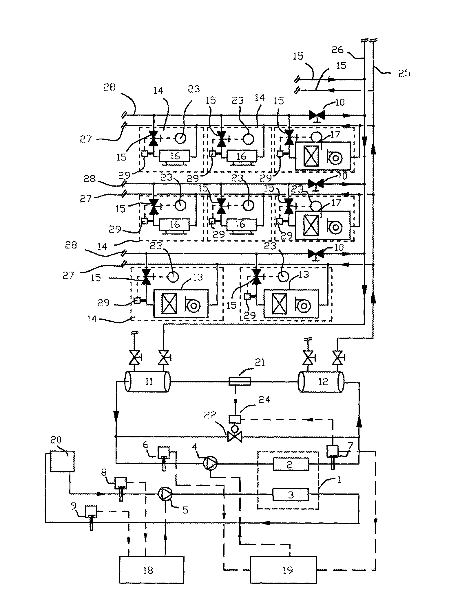
[0032]Refer to FIG. 1. A central air-conditioning system comprises a refrigerating unit 1, a cooling water loop, a cooling water pump 5 arranged on the cooling water loop, a cooling water pump frequency converter 18, a circulating water loop, a circulating water pump 4 arranged on the circulating water loop, a circulating water pump frequency converter 19, a plurality of circulating water branches arranged in parallel on the circulating water loop as well as temperature controllers 23, tail-end fan coils 16, fresh air units 17 and air handling units 13 arranged in rooms 14, the circulating water loop includes a water inlet manifold 25 and a water return manifold 26, and each circulating water branch includes a water inlet branch pipe 27 and a water return branch pipe 28; the tail-end fan coils 16, the fresh air units 17 and the air handling units 13 are arranged in parallel on the circulating water branches respectively; a regional flow balancing valve 10 for controlling the flow of...

embodiment 2

[0046]Refer to FIG. 3. A central air-conditioning system comprises a refrigerating unit 1, a cooling water loop, a cooling water pump 5 arranged on the cooling water loop, a cooling water pump frequency converter 18, a circulating water loop, a circulating water pump 4 arranged on the circulating water loop, a circulating water pump frequency converter 19, a plurality of circulating water branches arranged in parallel on the circulating water loop, as well as temperature controllers 23, tail-end fan coils 16, fresh air units 17 and air handling units 13 arranged in rooms 14, wherein the circulating water loop includes a water inlet manifold 25 and a water return manifold 26, and each circulating water branch includes a water inlet branch pipe 27 and a water return branch pipe 28; the tail-end fan coils 16, the fresh air units 17 and the air handling units 13 are arranged in parallel on the circulating water branches respectively; a regional flow balancing valve 10 for controlling th...

embodiment 3

[0060]Refer to FIG. 5, which shows another central air-conditioning system, comprising a refrigerating unit 1, a cooling water loop, a cooling water pump 5 arranged on the cooling water loop, a cooling water pump frequency converter 18, a circulating water loop, a circulating water pump 4 arranged on the circulating water loop, a circulating water pump frequency converter 19, a plurality of circulating water branches arranged in parallel on the circulating water loop, as well as temperature controllers 23, tail-end fan coils 16, fresh air units 17 and air handling units 13 arranged in rooms 14, wherein the circulating water loop includes a water inlet manifold 25 and a water return manifold 26, and each circulating water branch includes a water inlet branch pipe 27 and a water return branch pipe 28; the tail-end fan coils 16, the fresh air units 17 and the air handling units 13 are arranged in parallel on the circulating water branches respectively; a regional flow balancing valve 1...


PUM


Abstract

In a central air-conditioning system, regional flow balancing valves for controlling flow of water return branch pipes are arranged on the water return branch pipes, and energy balancing valves are arranged on water return pipes of tail-end fan coils respectively. A control method includes: detecting flow in the water return branch pipes, and adjusting the flow in the return branch pipes to be smaller than or equal to a branch pipe set flow value; and detecting the temperature of return water in the water return pipes of the tail-end fan coils, controlling the temperature of the return water in the water return pipes of the tail-end fan coils to be greater than or equal to a tail-end return water set temperature value, detecting the room temperature and adjusting the opening degree of the energy balancing valves in temperature controllers.

Description

FIELD OF THE INVENTION[0001]The present invention relates to a balance control technology for a central air-conditioning system, and in particular relates to a water balance control technology for a heating, ventilation and air-conditioning system.BACKGROUND OF THE INVENTION[0002]The main object of setting a central air-conditioning system is to obtain a comfortable indoor environment, and common central air-conditioning systems mostly adopt circulating water pipelines arranged in a direct return transmission and distribution manner, so that the following several problems always emerge in use: 1, the required temperature can not be always obtained in all tail-end rooms, and particularly after the local tail-end heat load is changed, the temperature can not be timely adjusted to the required temperature; 2, even if a cold or heat production device has enough capacity, a phenomenon of heat unevenness still appears in the system; 3, when the room temperature reaches a required value, t...

Claims


Application Information

Patent Timeline
IPC IPC(8): F25D17/02F25D29/00
CPCF25D29/00F25D17/02F24D11/0214F24D19/1015F24D2220/2027F24F11/83F24F11/85F24F11/84Y02B30/12
Inventor TAN, ZHONGXI
Owner TAN ZHONGXI
Why Eureka
Try Eureka