Plasma display panel with superior light-emitting characteristics, and method and apparatus for producing the plasma display panel

Inactive Publication Date: 2005-02-17
PANASONIC CORP
View PDF6 Cites 13 Cited by
  • Summary
  • Abstract
  • Description
  • Claims
  • Application Information

AI Technical Summary

Benefits of technology

[0028] In the actual manufacturing procedure, each of such heating processes is performed using a heating furnace. Conventionally, the sealing material temporary baking process, the bonding process, and the exhausting process are separately performed, and the panels are cooled to room temperature at each interval

Problems solved by technology

A problem of the PDP manufactured as above is how to improve the luminance and other light-emitting characteristics.
However, the prod

Method used


Image

  • Plasma display panel with superior light-emitting characteristics, and method and apparatus for producing the plasma display panel
  • Plasma display panel with superior light-emitting characteristics, and method and apparatus for producing the plasma display panel
  • Plasma display panel with superior light-emitting characteristics, and method and apparatus for producing the plasma display panel

Examples


example 1

[0133]

TABLE 1PANEL CONSTRUCTION AND LIGHT-EMITTING CHARACTERISTICSPARTIALPEAK NUMBERPRESSURE OFOF MOLECULESSTEAM VAPOR ININ H2O GASATMOSPHERIC GAS(Torr)COLORPEAKDESORBEDAXIS LENGTHTEMPO-TEMPERATUREINTENSITYFROM BLUERATIORARILYWHEN LIGHTRATIO OFFLUORESCENTOF BLUEBAKINGIS EMITTEDSPECTRUMSUBSTANCE ATFLUORESCENTBAKINGSEALINGPANELFROM ALLOF BLUE AND200° C. ORSUBSTANCEPANELFLUORESCENTGLASSBONDINGLUMINANCECELLS ONGREEN LIGHTMORE WITHCRYSTALNo.SUBSTANCEFRITPANELS(cd / m2)PANEL (k)(BLUE / GREEN)TDS ANALYSIS(c-AXIS / a-AXIS)112.012.012.049571000.801.0 × 10164.0218028.08.08.052075000.887.9 × 10154.0217733.03.03.054084001.025.3 × 10154.0217240.00.00.055090001.102.2 × 10154.02164520.020.020.047063000.762.6 × 10164.02208

[0134] In Table 1, the panels 1 to 4 are PDPs manufactured based on the present embodiment. The panels 1 to 4 have been manufactured in different partial pressures of the steam vapor in the dry air flown during the flourescent substance layer baking process, frit temporary baking proces...

example 2

[0176]

TABLE 2PANEL LIGHT-EMITTING CHARACTERISTICSPEAK NUMBERPEAK INTENSITYOF MOLECULES IN H2OAXIS LENGTHCOLOR TEMPERATURERATIO OFGAS DESORBED FROMRATIO OF BLUEWHEN LIGHT IS EMITTEDSPECTRUMBLUE FLUORESCENTFLUORESCENTPANELFROM ALL CELLS ONOF BLUE ANDSUBSTANCE ATSUBSTANCEPANELLUMINANCEPANELGREEN LIGHT200° C. OR MORE WITHCRYSTALNo.(cd / m2)(k)(BLUE / GREEN)TDS ANALYSIS(c-AXIS / a-AXIS)654084000.946.3 × 10154.02175750072000.838.8 × 10154.02177847063000.762.6 × 10164.02208

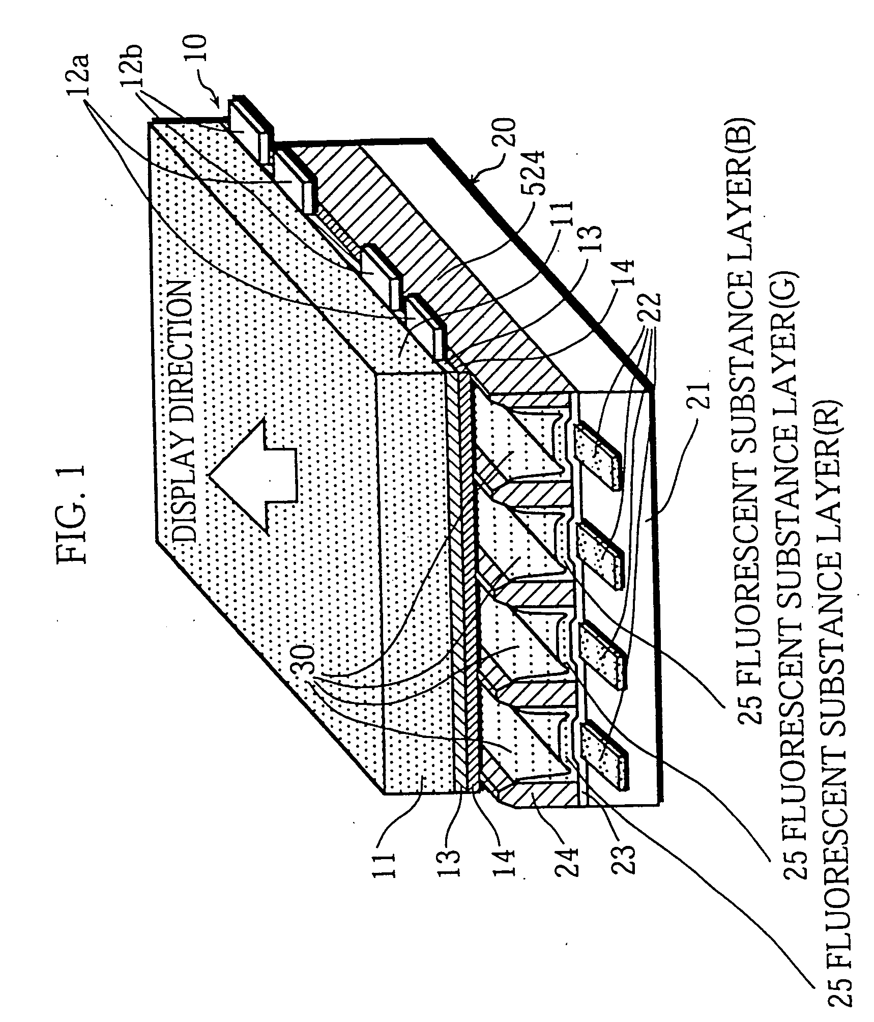
[0177] The panel 6 is a PDP manufactured based on FIG. 10 of the present embodiment in which the partial pressure of the steam vapor in the dry air flown during the bonding process is set to 2 Torr (the dew-point temperature of the dry air is set to −10).

[0178] The panel 7 is a PDP manufactured partially based on FIG. 15 of the present embodiment in which each of the gaps 63a and 63b has less width than each of the gaps 64a and 64b between the vertical sealing area 61 and the adjacent partition wall 24 (so that D1, D21, d2 is...

example 3

[0207]

TABLE 3PANEL BONDING CONDITIONS ANDLIGHT-EMITTING CHARACTERISTICSPARTIALTEMPERATURERELATIVEPRESSUREPRESSUREFOR REDUCINGLIGHT-OF STEAMIN SPACETO BE LOWEREMITTINGVAPOR INBETWEENTHANINTENSITYCHROMATICITYPIANELDRY GASPANELSATMOSPHERICOF BLUECOORDINATENo.DRY GAS TYPE(Torr)(Torr)PRESSURE(° C.)LIGHTY OF BLUE LIGHT11AIR125003701080.07512AIR85003701150.06813AIR35003701200.06314AIR05003701250.05815AIR03003701200.05816AIR01003701130.05817AIR0500ROOM1210.062TEMPERATURE18AIR05003201230.06019AIR05004201270.05620NITROGEN05003701050.05821Ne-Xe(%)05003701050.05822AIR0ATMOSPHERIC—1250.058PRESSURE23——ATMOSPHERIC—1000.090PRESSUREPEAK NUMBERPEAK INTENSITYOF MOLECULES IN H2OAXIS LENGTHPEAKRATIO OFGAS DESORBED FROMRATIO OF BLUEWAVELENGTHCOLORSPECTRUMBLUE FLUORESCENTFLUORESCENTOFTEMPERATUREOF BLUE ANDSUBSTANCE ATSUBSTANCEPIANELBLUE LIGHTIN WHITEGREEN LIGHT200° C. OR MORE WITHCRYSTALNo.(nm)BALANCE(K)(BLUE / GREEN)TDS ANALYSIS(c-AXIS / a-AXIS)1145571000.821.0 × 10164.021801245476000.887.9 × 10154.021771345...


PUM


Abstract

A PDP with superior light-emitting characteristics and color reproduction is achieved by setting the chromaticity coordinate y (the CIE color specification) of light to 0.08 or less, more preferably to 0.07 or less, or 0.06 or less, enabling the color temperature of light to be set to 7,000K or more, and further to 8,000K or more, 9,000K or more, or 10,000K or more. The PDP is manufactured by a method in which the processes for heating the fluorescent substances such as the fluorescent substance baking, sealing material temporary baking, bonding, and exhausting processes are performed in the dry gas atmosphere, or in an atmosphere in which a dry gas is circulated at a pressure lower than the atmospheric pressure. This PDP is also manufactured by: a method in which after the front and back panels are bonded together, the exhausting process for exhausting gas from the inner space between panels is started while the panels are not cooled to room temperature; or a method in which after the front and back panels are temporarily baked, the process for bonding the panels is started while the panels are not cooled to room temperature. This reduces the time and energy required for heating, resulting in reduction of manufacturing cost.

Description

FIELD OF THE INVENTION [0001] This invention relates to a plasma display panel used as a display for a color television receiver or the like, and also relates to a method of producing the plasma display panel. BACKGROUND OF THE INVENTION [0002] Recently, Plasma Display Panel (PDP) has received attention as a large-scale, thin, lightweight display for use in computers and televisions, and the demand for high-definition PDPs has also increased. [0003]FIG. 29 is a sectional view showing a general AC-type PDP. [0004] In the drawing, a front glass substrate 101 is covered by a stack of display electrodes 102, a dielectric glass layer 103, and a dielectric protecting layer 104 in the order, where the dielectric protecting layer 104 is made of magnesium oxide (MgO) (see, for example, Japanese Laid-Open Patent Application No. 5-342991. [0005] Address electrodes 106 and partition walls 107 are formed on a back glass substrate 105. Fluorescent substance layers 110 to 112 of respective colors ...

Claims


Application Information

Patent Timeline
IPC IPC(8): H01J9/24H01J9/26H01J9/38H01J9/385H01J17/49
CPCH01J9/241H01J9/261H01J9/38H01J9/385H01J2211/48H01J11/36H01J11/42H01J11/48H01J11/54H01J11/12H01J9/24
Inventor KADO, HIROYUKIOHTANI, MITSUHIROAOKI, MASAKIMIYASHITA, KANAKO
Owner PANASONIC CORP
Why Eureka
Try Eureka