Projectile trajectory control system

a control system and trajectory technology, applied in direction controllers, instruments, weapons, etc., can solve the problems of affecting the rotational motion of the control section relative to the weapon system, and achieve the effects of reducing weight, low power consumption, and rotating ra

Active Publication Date: 2008-04-08
GEN DYNAMICS ORDNANCE & TACTICAL SYST
View PDF44 Cites 64 Cited by
  • Summary
  • Abstract
  • Description
  • Claims
  • Application Information

AI Technical Summary

Benefits of technology

[0009]One advantage of using a dissipative braking system is reduced weight and very low power consumption for de-spinning the guidance section compared to using an electric motor / generator, which requires an armature, windings, magnets, etc. Another advantage is that the asymmetric aero-surfaces used for control surfaces do not require control actuators in order to change the direction of the projectile. Another advantage is that a control system using fixed aero-surfaces, such as strakes, and a braking system is capable of rotating trajectory control surfaces to a predetermined rotational speed, which may be less or more than the rotational speed of the body of a weapon system. At the predetermined rotational speed, the fins do not substantially alter the direction of the projectile; however, the control system may be de-spun rapidly from the predetermined rotational speed for the purpose of course correction. A balance between the dissipative braking system and torque provided by strakes is capable of maintaining a rotation rate of the control surfaces substantially less than the rotation rate of a spin stabilized projectile, reducing the energy and time needed to de-spin the control surfaces for the purpose of course correction. Yet another advantage is the ability to keep all of the control electronics within the weapon system itself, while the rate of rotation of a counter-rotating trajectory control system is determined using existing and future sensing technology capable of determining the relative rate of rotation and orientation between the control surfaces and the weapon system. In one example, this permits the trajectory control of a non-spinning weapon system, and the non-spinning weapon system may include two counter-rotating sections that balance torques of braking and spin up of the trajectory control system.

Problems solved by technology

The control section may be coupled to the weapon system such that rotational motion of the control section relative to the weapon system may be impeded by a dissipative braking system.

Method used


Image

  • Projectile trajectory control system
  • Projectile trajectory control system
  • Projectile trajectory control system

Examples


Embodiment Construction

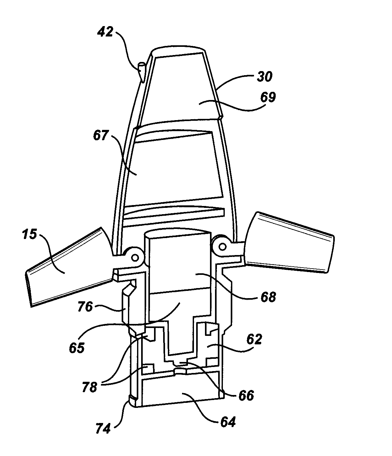
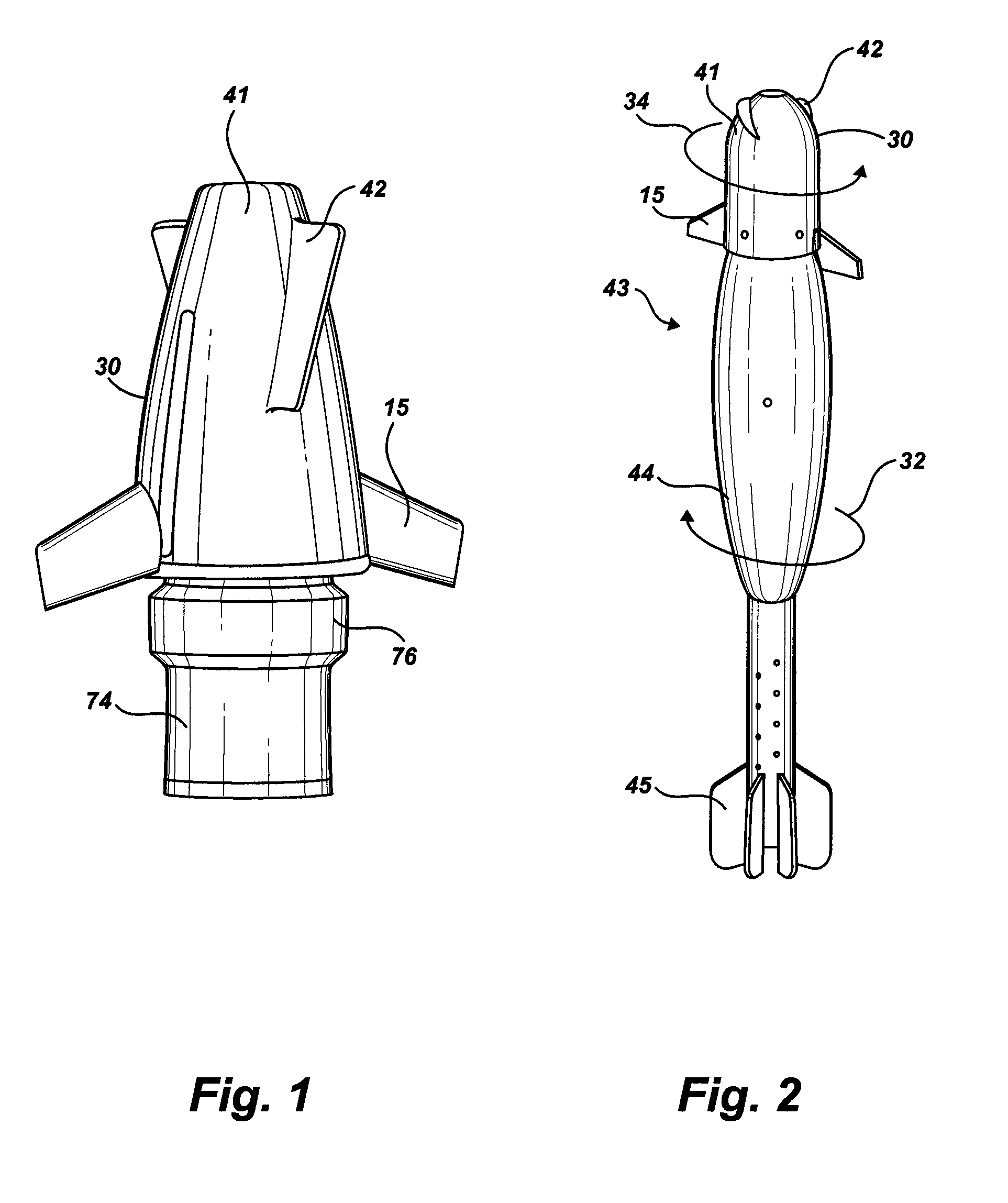
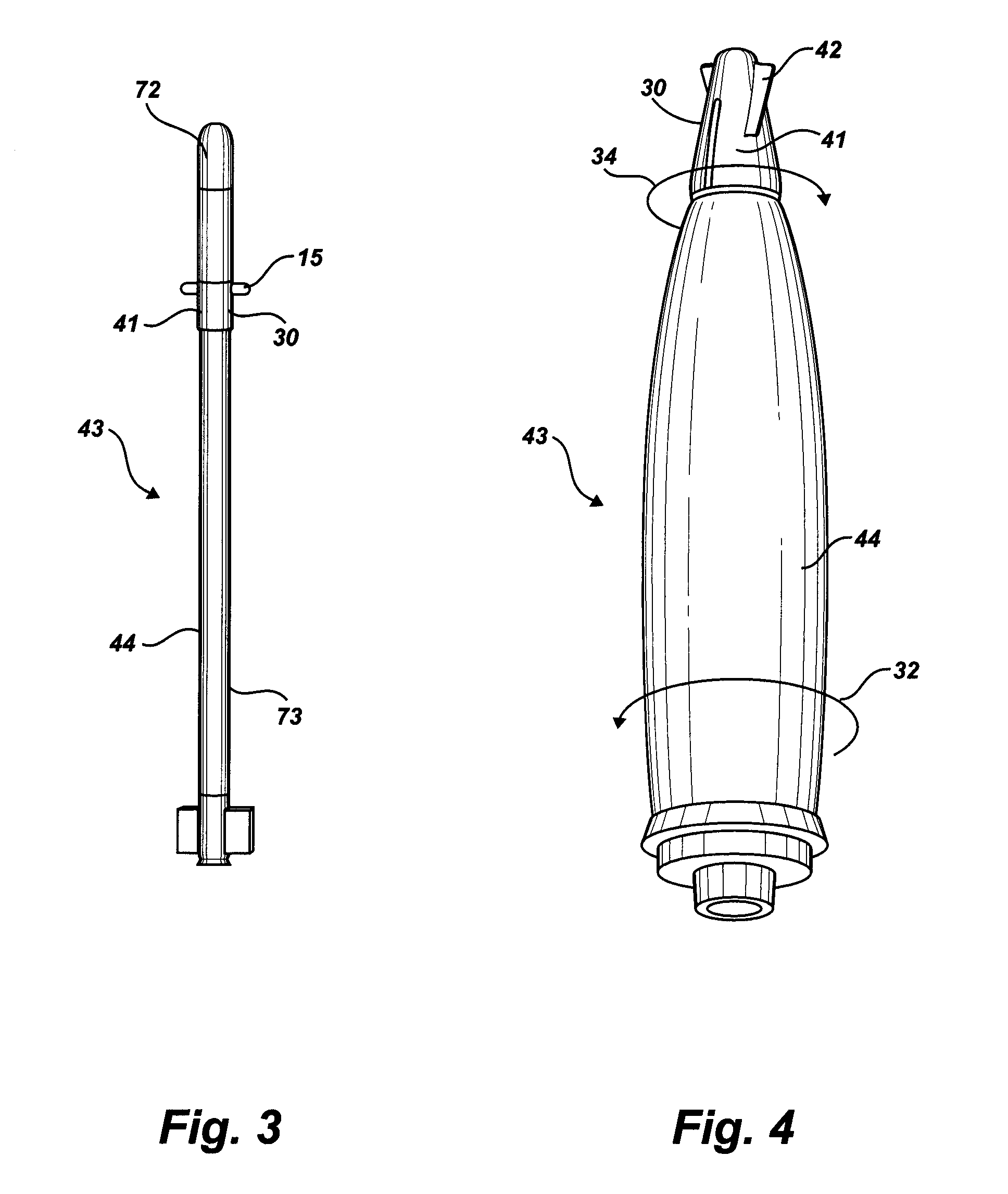
[0020]The following description is intended to convey a thorough understanding of the invention by providing a number of specific embodiments and details involving a projectile trajectory control system. It is understood, however, that the invention is not limited to these specific embodiments and details, which are exemplary only. It is further understood that one possessing ordinary skill in the art, in light of known systems and methods, would appreciate the use of the invention for its intended purposes and benefits in any number of alternative embodiments.

[0021]Throughout this specification, the term “reference frame” is used in association with embodiments of the invention. “Reference frame” refers to any appropriate coordinate system or frame of reference with respect to which a projectile movement or rotation could be measured. For example, the reference frame may be an Earth inertial frame, but any known frame of reference may be used.

[0022]Embodiments of the present invent...


PUM


Abstract

Trajectory is controlled by a control system having fins that de-spin a section of the control system relative to a projectile or missile. The control system also includes aero-surfaces that produce a lift when brought to rotation speed of about 0 Hz relative to a reference frame and a brake that couples the guidance package to the rotational inertia of the projectile or missile. In one example, no electric motor is used in the trajectory control system, saving weight and increasing reliability.

Description

CROSS REFERENCE[0001]The present application claims priority under 35 U.S.C. § 119(e) to U.S. Provisional Patent Application Ser. No. 60 / 715,673, filed Sep. 9, 2005, which is hereby incorporated by reference in its entirety.FIELD OF THE INVENTION[0002]The field relates to projectile trajectory control for a projectile or rocket having a guidance system.BACKGROUND[0003]It is known to stabilize a projectile by spinning the projectile along a longitudinal axis while in flight. It is also known to provide a projectile with a control system capable of directing the trajectory of the projectile to some degree during the flight of the projectile. One of skill in the art will recognize that the control system could be made simpler and / or more effective if the control system could be de-spun with respect to the projectile body. Accordingly, it is known to de-spin a projectile control system using an electric motor.[0004]U.S. Pat. Nos. 4,565,340 to Bains and 6,981,672 to Clancy, et al., descr...

Claims


Application Information

Patent Timeline
Patent Type & Authority Patents(United States)
IPC IPC(8): F42B10/02F41G7/00F42B10/00
CPCF42B10/54F42B10/60
Inventor MORRIS, JOSEPH P.SMITH, DOUGLAS L.
Owner GEN DYNAMICS ORDNANCE & TACTICAL SYST
Why Eureka
Try Eureka