Rocket landing systems

Active Publication Date: 2016-10-27
KNUDSEN N ERIC +3
View PDF1 Cites 23 Cited by
  • Summary
  • Abstract
  • Description
  • Claims
  • Application Information

AI Technical Summary

Problems solved by technology

After carrying their payload to the edge of or into outer space, the rockets or rocket boosters have fallen back to earth only to crash into the ground or the ocean and as a result are destroyed.

Method used


Image

  • Rocket landing systems
  • Rocket landing systems
  • Rocket landing systems

Examples


Embodiment Construction

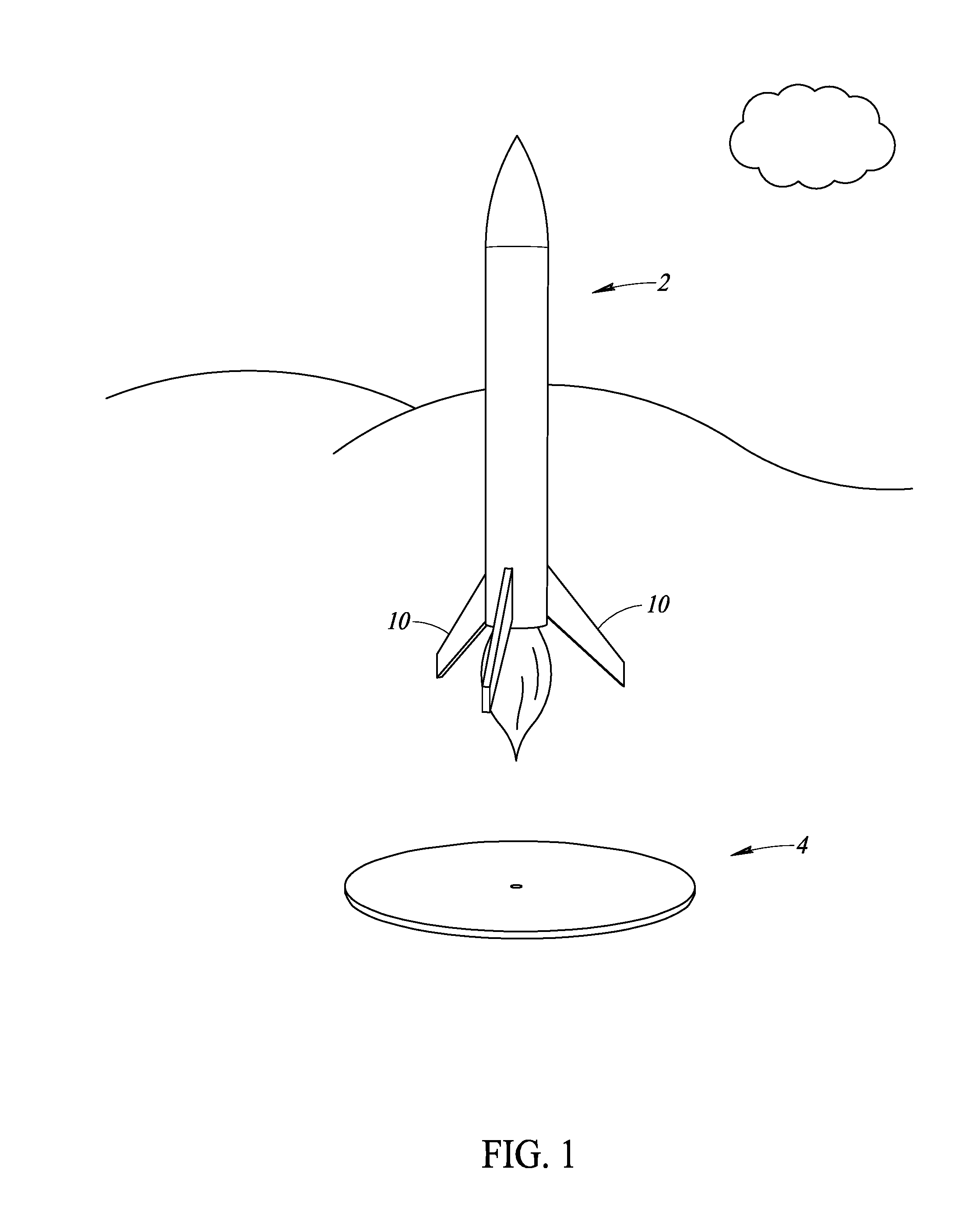
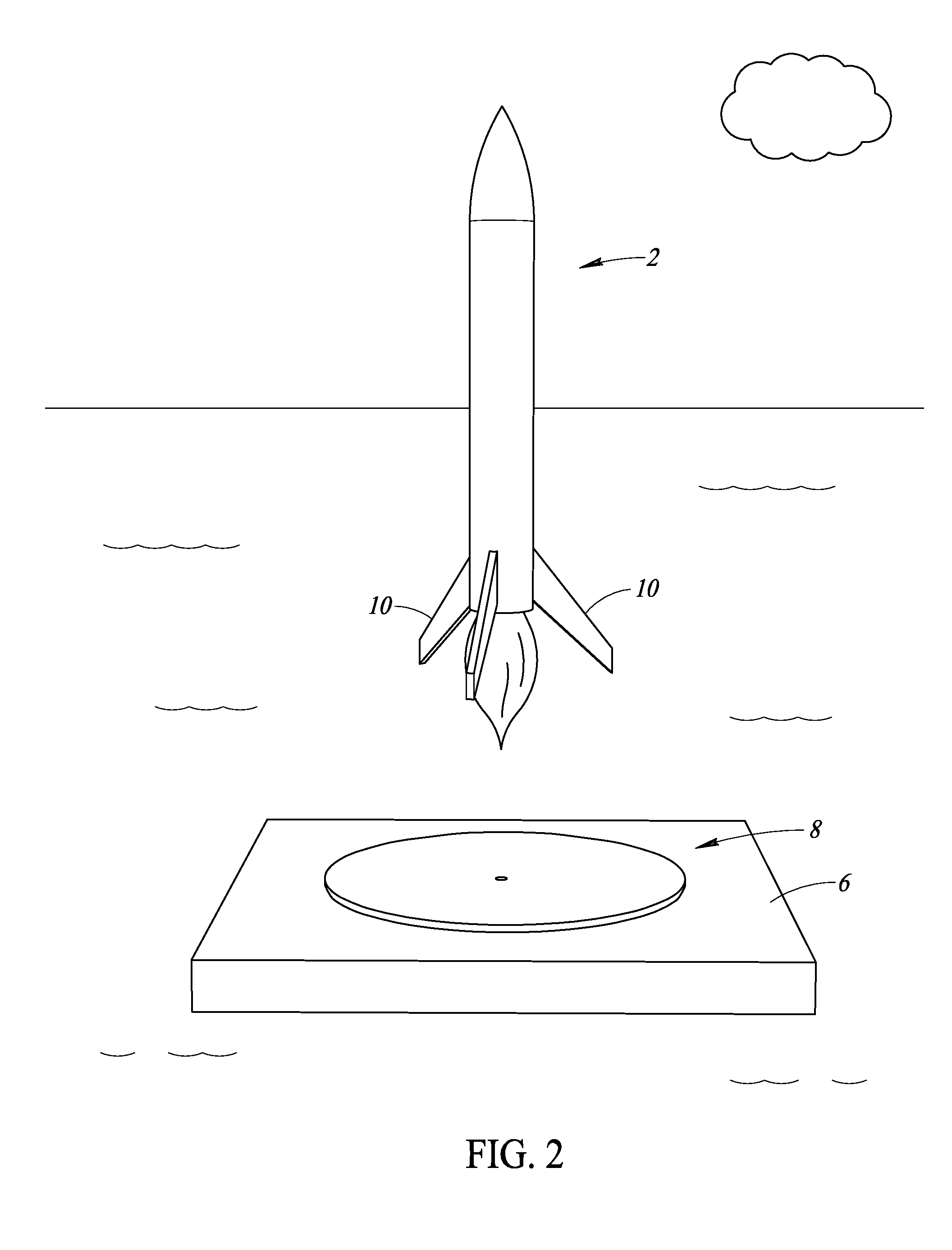
[0022]FIG. 1 illustrates a rocket 2 landing on the ground at a land-based landing site 4. FIG. 2 illustrates the rocket 2 landing on a barge 6 in the ocean at a sea-based landing site 8. In both a land-based and a sea-based landing, the rocket 2 includes landing gear 10 that can help the rocket 2 come to rest at the landing site. Because of the relatively small width to height ratio of the landing gear 10 relative to the overall height of the rocket 2, and because the center of mass of the rocket 2 can be higher than desired when the rocket 2 is attempting to land at a landing site, the rocket 2 can be prone to tip over, causing damage to or destruction of the rocket 2.

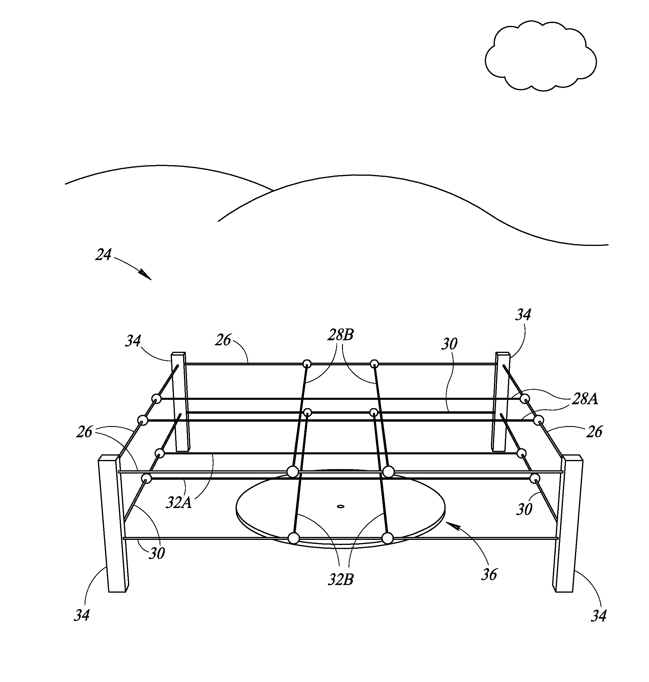
[0023]Therefore, as shown in FIG. 3, a rocket stabilizing structure 12 can be used to stabilize the rocket 2 as it attempts to land at a landing site 14. While landing site 14 is illustrated as a land-based landing site 14, landing site 14 can in alternative embodiments be a sea-based landing site 14. The stabilizing ...


PUM


Abstract

A rocket landing stabilization system can include one or more upright support structures such as posts, columns, or walls, from which one or more stabilizing elements can be supported. The stabilizing elements can be used to stabilize a rocket as it lands at a landing site. The rocket landing stabilization system can also include a cradle, funnel, or cone to catch or otherwise support a rocket as it lands at the landing site. The rocket landing stabilization system can be located on land or at sea.

Description

BACKGROUND[0001]1. Technical Field[0002]The present disclosure relates to systems for safely landing a rocket or a rocket booster for reuse, for example, after the rocket booster has been used to launch a payload into outer space.[0003]2. Description of the Related Art[0004]Since the dawn of the space age and the launching of Sputnik into outer space, various rockets have been used to launch cargo, animals, and humans into outer space. After carrying their payload to the edge of or into outer space, the rockets or rocket boosters have fallen back to earth only to crash into the ground or the ocean and as a result are destroyed. In recent years, some have attempted to bring rocket boosters back safely from their mission so they can be reused. Some believe that reusable rockets or rocket boosters could reduce the costs associated with launching objects into outer space significantly. Example rocket landing techniques are shown and described in U.S. Pat. No. 8,678,321, which is incorpo...

Claims


Application Information

Patent Timeline
Patent Type & Authority Applications(United States)
IPC IPC(8): B64F1/02B64G1/62B63B35/53B64G5/00
CPCB64F1/02B63B35/53B64G1/62B64G5/00B64G2005/005
Inventor KNUDSEN, N. ERICKNUDSEN, MATTHEW NIELSKNUDSEN, ANDREW NIELSKNUDSEN, JACOB NIELS
Owner KNUDSEN N ERIC
Why Eureka
Try Eureka