Multilayer armor system for defending against missile-borne and stationary shaped charges

Inactive Publication Date: 2011-03-24
FORCE PROTECTION TECH
View PDF9 Cites 45 Cited by
  • Summary
  • Abstract
  • Description
  • Claims
  • Application Information

AI Technical Summary

Benefits of technology

[0020]In accordance with a third aspect of the present invention, there is disclosed a method of defeating missile-borne and stationary shaped charges directed at a vehicle, the missile of the type having a conical forward portion, relative to its trajectory, and a tip-mounted electric fuze component, the vehicle having a hull with an outer surface. The method includes the steps of interposing a grid layer comprised of a net or spaced bar / slat configuration in the missile trajectory spaced from the outer surface of a vehicle, the grid layer having a grid mesh size to engage the conical section to short circuit the fuze on a missile not detonating on the grid layer; interposing a shaped fiber-reinforced material layer downstream of the grid layer relative to the trajectory, the shaped fiber-reinforced layer having depressions therein and bulging armor with metal plates disposed on the surfaces forming the depressions, the depressions configured such that a jet formed by a missile detonating on the grid layer next encounters the bulging armor and the shaped layer material; moving the metal plates of the bulging armor obliquely into the path of the jet by a reaction of the impinging jet; deflecting the jet with the metal plates moved into its path; and attenuating the deflected jet in the fiber-reinforced materials of the shaped layer.

Problems solved by technology

The problem is that these explosive systems are poor at defeating EFP or Hybrid systems.
Such an occurrence can, obviously, have very significant detrimental effects on the systems and personnel within a vehicle having its armor defeated in such a manner.
For that reason, and the fact such weapons are effective, has proved troublesome to vehicles using conventional armor.
While any anti-armor projectile can be defeated by metal armor of sufficient strength and thickness, extra metal armor thickness is heavy and expensive, adds weight to any armored vehicle using it which, in turn, places greater strain on the vehicle engine, and drive train.

Method used


Image

  • Multilayer armor system for defending against missile-borne and stationary shaped charges
  • Multilayer armor system for defending against missile-borne and stationary shaped charges
  • Multilayer armor system for defending against missile-borne and stationary shaped charges

Examples


Embodiment Construction

[0033]Reference will now be made in detail to embodiments of the invention, examples of which are illustrated in the accompanying drawings. Wherever possible, the same reference numbers will be used throughout the drawings to refer to the same or like parts.

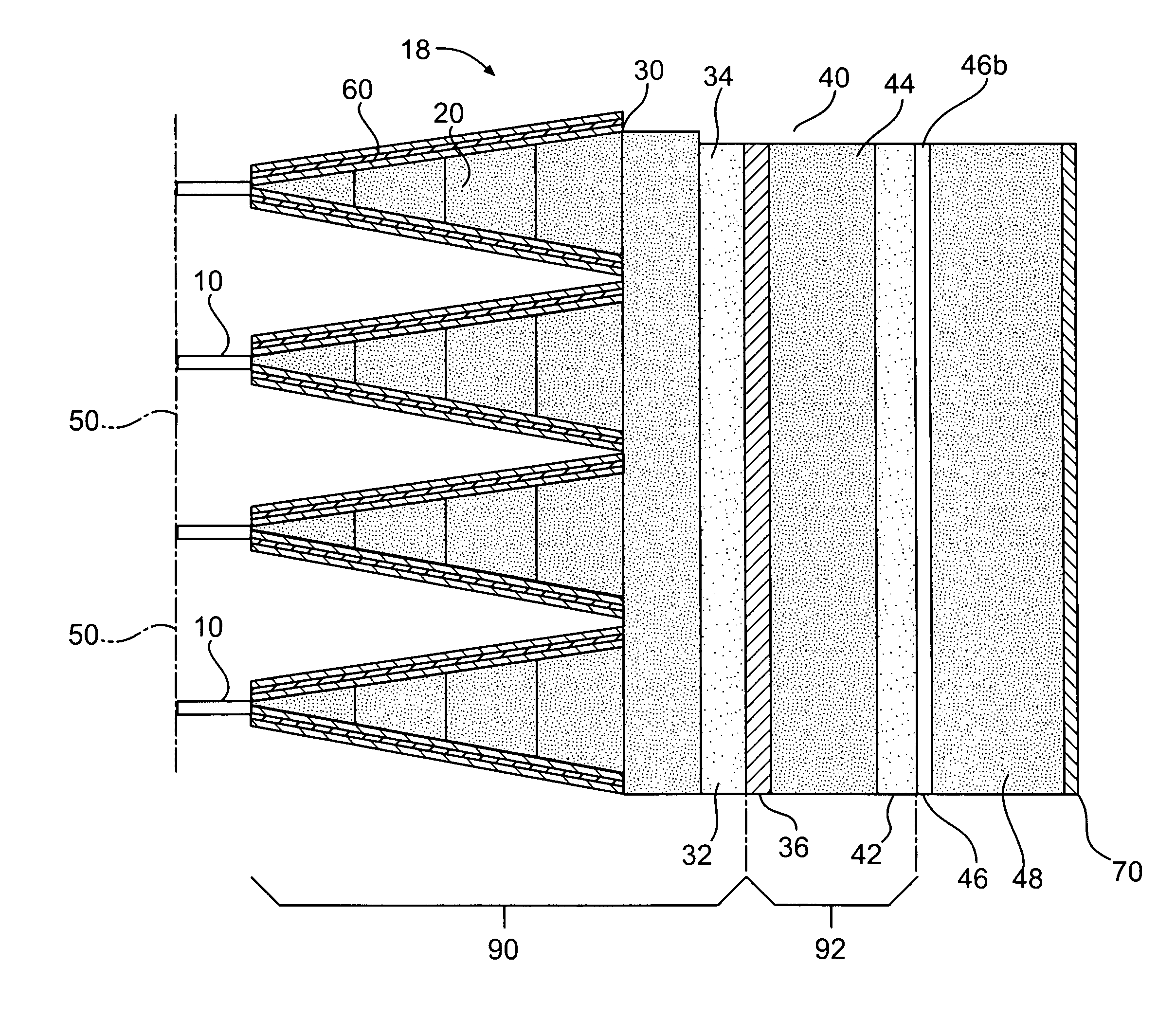
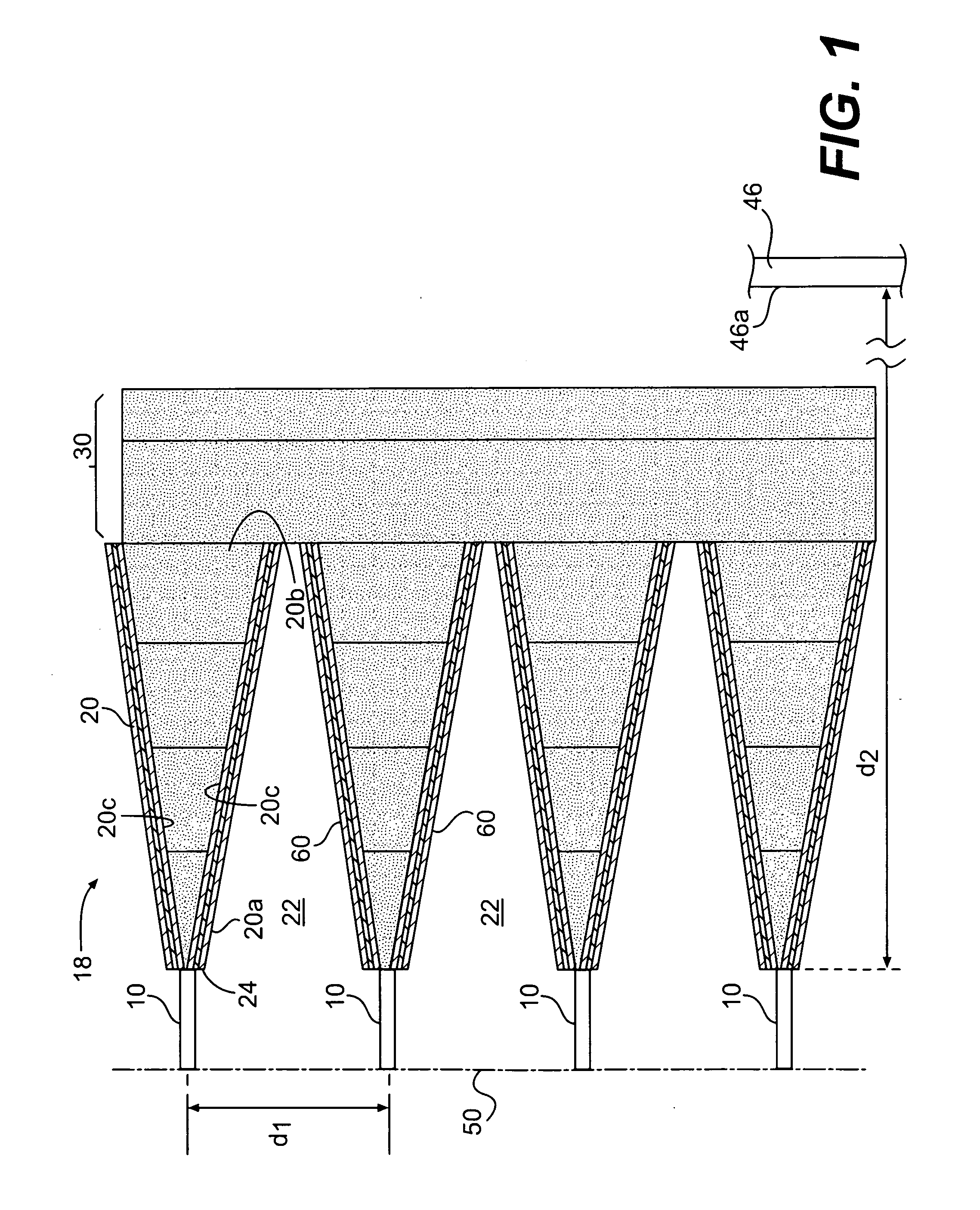
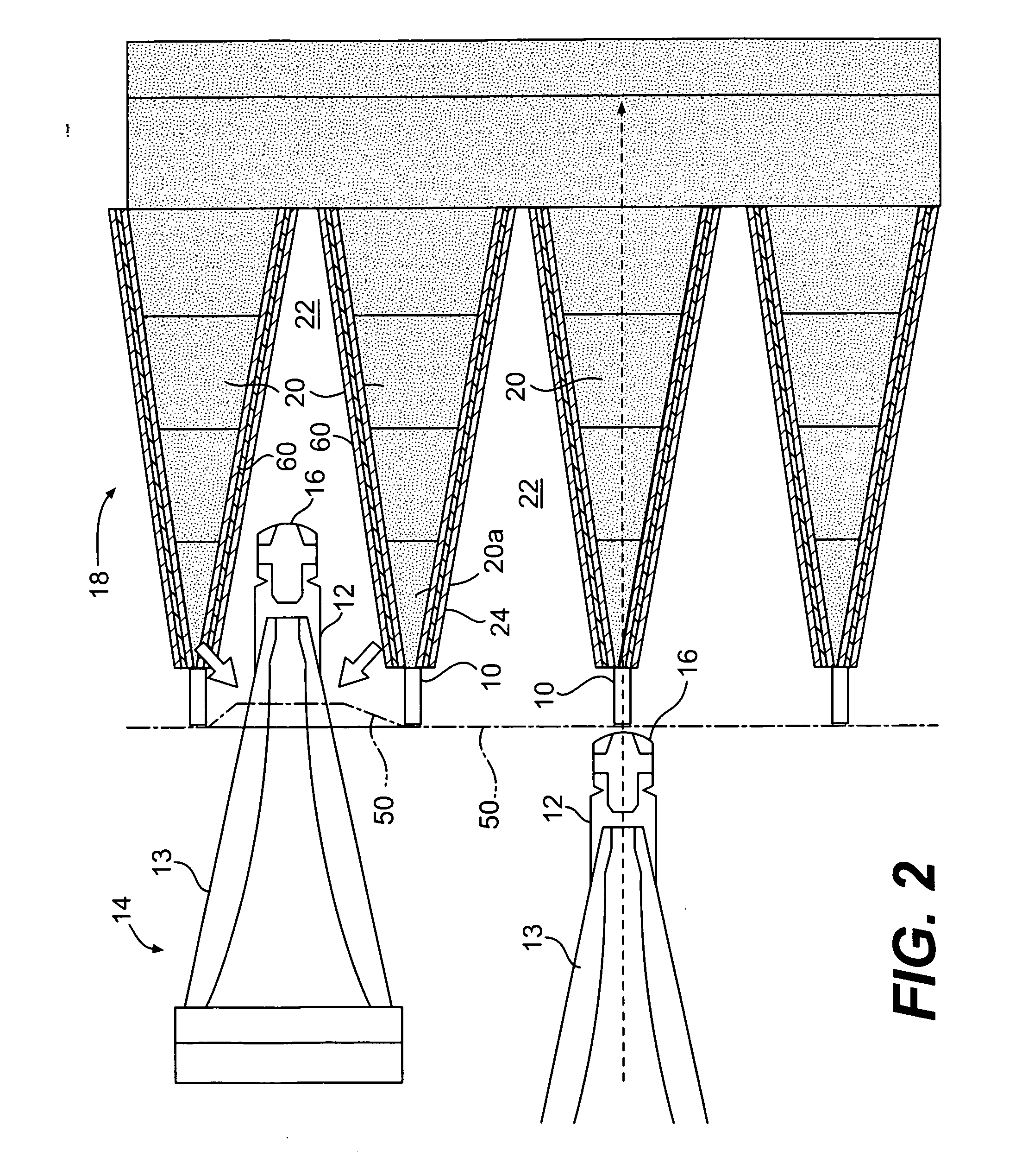
[0034]In accordance with the invention, there is provided an armor system for defeating a range of anti-armor weapons. While the invention and its embodiments may impede penetration of relatively non-elongated, heavy, solid metal projectiles formed and propelled by either manufactured explosive devices or improvised explosive device, its primary utility is to defeat devices generating elongated metal “jets,” produced by shaped charges whether missile borne or stationary, along with the heavy solid projectiles.

[0035]The parameters of the system can be selected to defeat a particular projectile if its weight, density, velocity, and size are known. The parameters of the system are the mechanical properties (ultimate tensile strength...


PUM


Abstract

An armor system for defeating rocket propelled grenade-type missiles and / or high velocity jets created by shaped charges directed at a vehicle includes a grid layer such as a net and / or an array of slats or bars (“RPG”) spaced from an outer surface of the vehicle by support members. The grid layer has a characteristic mesh size or bar / slat spacing to disrupt the missile firing mechanism. The system also has a shaped layer having a plurality of tapered members formed from a fiber-reinforced material, the tapered members positioned between the grid layer and the vehicle outer surface and having respective apex ends proximate the distant the grid layer and base ends, the tapered members defining with adjacent tapered members a plurality of depressions opening in a direction to receive an incoming conical portion of an unexploded RPG-type missile, or a jet emanating from an exploded RPG or other anti-armor device, and a layer of fiber-reinforced material abutting the base ends of the tapered members. The system may further include reactive elements disposed on surfaces of the tapered members defining the depressions to deflect impinging jets. The system may still further include one or more metal armor layers and one or more additional fiber-reinforced material layers disposed between the shaped fiber-reinforced material layer and the vehicle surface.

Description

RELATED APPLICATIONS[0001]Priority is claimed to U.S. Provisional Applications No. 61 / 006,600, filed Jan. 23, 2008; No. 61 / 006,601, filed Jan. 23, 2008; No. 61 / 006,643, filed Jan. 24, 2008; No. 61 / 006,649, filed Jan. 25, 2008; and No. 61 / 064,234, filed Feb. 22, 2008, the disclosures of each of which being incorporated by reference.FIELD OF THE INVENTION[0002]The present invention relates to an armor system that is resistant to penetration by high energy solid projectiles and jets of material from hollow charge weapons such as rocket propelled grenades (“RPG's”) and stationary shaped charger.BACKGROUND OF THE INVENTION[0003]Conventional armor such as for protecting vehicles is subjected to a variety of projectiles designed to defeat the armor by either penetrating the armor with a solid or jet-like object or by inducing shock waves in the armor that are reflected in a manner to cause spalling of the armor such that an opening is formed and the penetrator (usually stuck to a portion o...

Claims


Application Information

Patent Timeline
IPC IPC(8): F41H5/007F41H5/04F41H5/06F41H7/02
CPCF41H5/023F41H5/007
Inventor JOYNT, VERNON P.
Owner FORCE PROTECTION TECH
Why Eureka
Try Eureka