Counter rotation steering wheel

a technology of anti-rotation and steering wheel, which is applied in the direction of steering linkages, alternative steering control, transportation and packaging, etc., can solve the problems of limiting such functionality and requiring re-engagemen

Active Publication Date: 2016-11-03
STEERING SOLUTIONS IP HLDG
View PDF13 Cites 40 Cited by
  • Summary
  • Abstract
  • Description
  • Claims
  • Application Information

AI Technical Summary

Benefits of technology

[0006]In yet another embodiment of the disclosure, a steering column assembly configured to couple to a steering wheel is provided. The assembly includes a steering column shaft having a first end and a second end, the second end configured to couple to the steering wheel. The assembly also includes an intermediate shaft coupled to the steering column shaft first end. The assembl

Problems solved by technology

The steering wheel may be utilized for non-driving functions (e.g., tray table), but rotation of the steering wheel limits such functionality.
“De-clutching” the wheel, or an associa

Method used


Image

  • Counter rotation steering wheel
  • Counter rotation steering wheel

Examples


Embodiment Construction

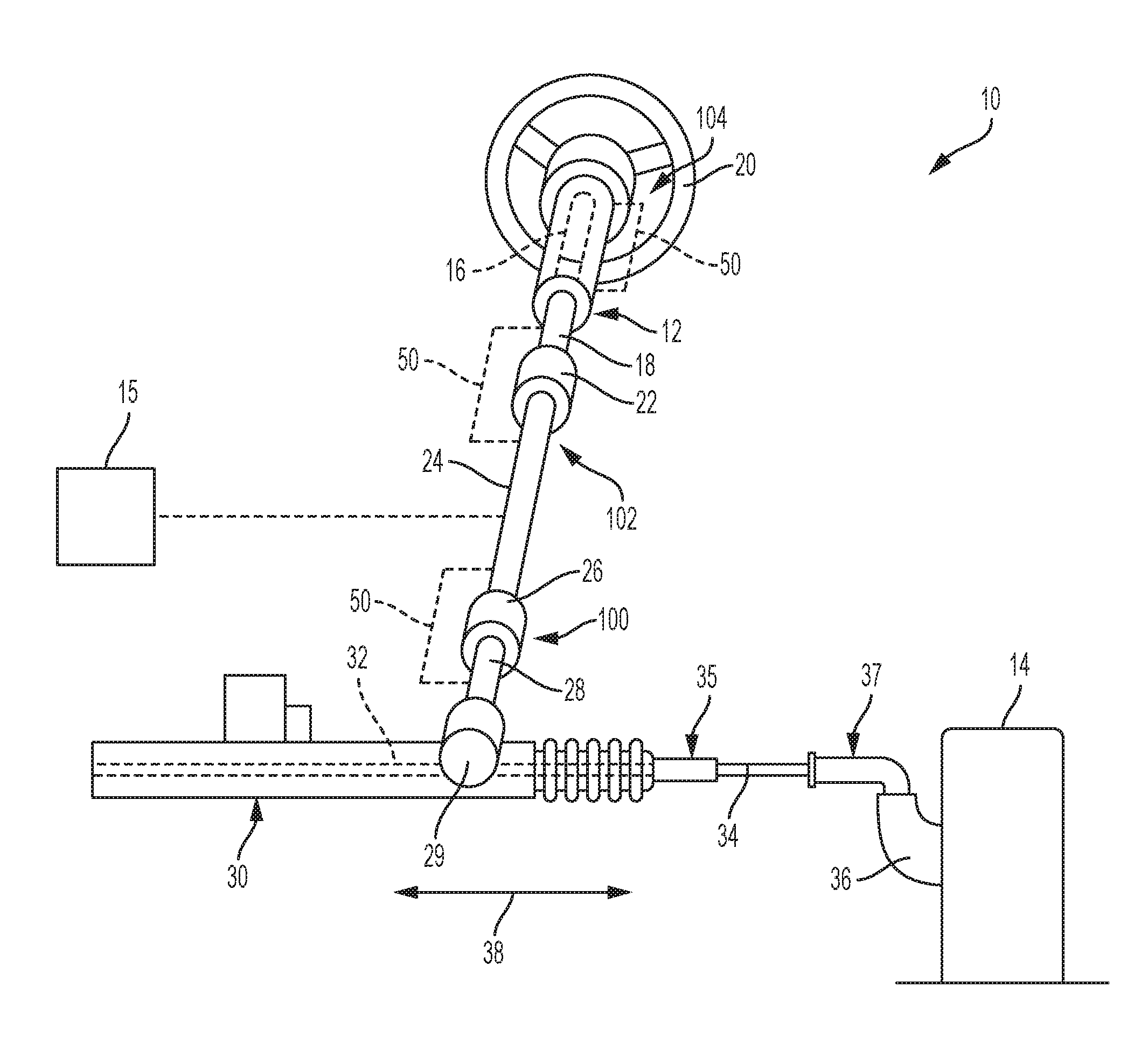
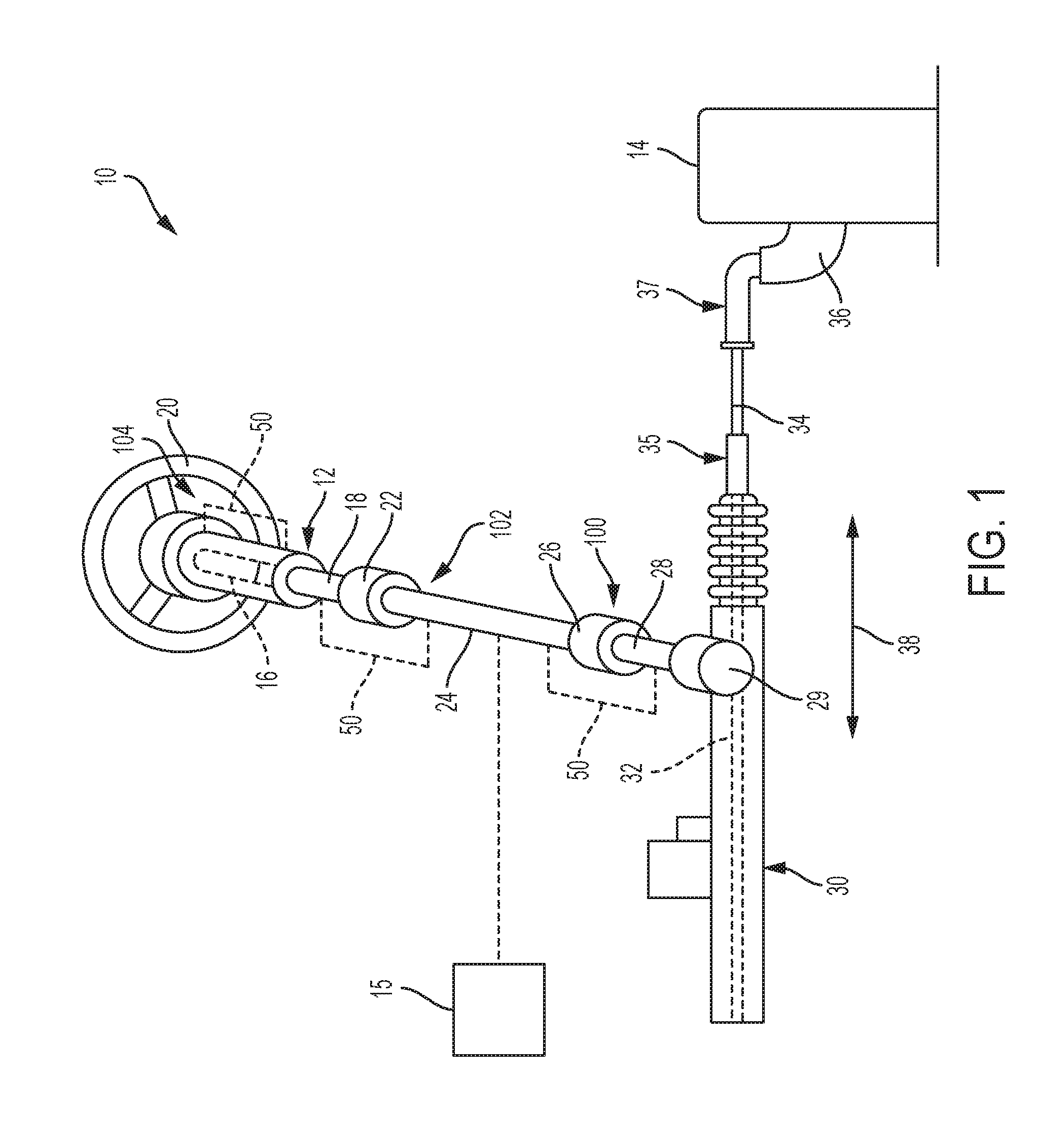
[0010]Referring now to the Figure, where the invention will be described with reference to specific embodiments, without limiting same, FIG. 1 illustrates an exemplary steering system 10 for use in a vehicle (not shown). Steering system 10 enables the operator of the vehicle to control the direction of the vehicle through the manipulation of a steering column assembly 12, which is mechanically connected to road wheels 14. Steering system 10 may also be equipped with a self-steering mechanism 15 such as an Advanced Driver Assistance System (ADAS) or the like.

[0011]Steering column assembly 12 generally includes an upper column shaft 16, a lower column shaft 18, a steering wheel 20, an intermediate shaft 24, and a steering gear assembly 30. In the exemplary embodiment, steering wheel 20 is disposed at upper column shaft 16, and steering column assembly 12 is movable between a deployed position and a stowed position. In the deployed position, the operator can apply a rotational force to...


PUM


Abstract

A steering column assembly configured to couple to a steering wheel is provided. The assembly includes a steering column shaft having a first end and a second end, the second end configured to couple to the steering wheel. The assembly also includes an intermediate shaft coupled to the steering column shaft first end. The assembly further includes a steering input pinion coupled to the intermediate shaft. The assembly yet further includes a counter rotation mechanism configured to counter rotate rotational movement of the steering column assembly such that the steering wheel does not rotate.

Description

CROSS REFERENCE TO RELATED APPLICATION[0001]This patent application claims priority to U.S. Provisional Patent Application Ser. No. 62 / 155,589, filed May 1, 2015, which is incorporated herein by reference in its entirety.BACKGROUND[0002]The disclosure herein relates to steering column assemblies and, more specifically, to a steering column assembly with anti-rotation features.[0003]When some vehicles are fitted with systems that allow the vehicle to be driven autonomously, the steering system(s) operate while the steering wheel may be required to rotate while the vehicle is in an autonomous driving mode. The steering wheel may be utilized for non-driving functions (e.g., tray table), but rotation of the steering wheel limits such functionality. “De-clutching” the wheel, or an associated intermediate component, from a steering gear results in disengagement of the wheel, thereby requiring re-engagement if an operator wishes to manually take control of the vehicle.SUMMARY OF THE INVENT...

Claims


Application Information

Patent Timeline
IPC IPC(8): B62D1/22B62D1/183B62D6/00
CPCB62D1/22B62D1/183B62D6/00B62D1/20B62D5/008
Inventor PATTOK, ERIC D.BODTKER, JOEN C.
Owner STEERING SOLUTIONS IP HLDG
Why Eureka
Try Eureka