Method for producing grain-oriented electrical steel sheet

a technology of electrical steel and grain, which is applied in the direction of heat treatment apparatus, magnetic bodies, furnaces, etc., can solve the problems of large deviation of iron loss property resulting from temperature variation inside the steel sheet in heating, and the inability to achieve the desired effect of rapid heating

Active Publication Date: 2016-11-03
JFE STEEL CORP
View PDF1 Cites 5 Cited by
  • Summary
  • Abstract
  • Description
  • Claims
  • Application Information

AI Technical Summary

Benefits of technology

[0017]According to the invention, grain-oriented electrical steel sheets being low in the iron loss and small in the deviation of iron loss values can be provided by holding the steel sheet in a temperature zone causing the recovery for a given time when rapid heating is performed in the decarburization annealing.

Problems solved by technology

According to the inventors' knowledge, however, when the heating rate becomes high, the deviation of the iron loss property resulting from temperature variation inside the steel sheet in heating becomes large.
However, if the iron loss deviation is large, the average value of iron loss values over the full width of the steel sheet becomes high as compared to that in best site, and hence the desired effect by the rapid heating is not obtained.

Method used


Image

  • Method for producing grain-oriented electrical steel sheet
  • Method for producing grain-oriented electrical steel sheet

Examples


example 1

[0052]A steel slab comprising C: 0.070 mass %, Si: 3.35 mass %, Mn: 0.10 mass %, Al: 0.025 mass %, Se: 0.025 mass %, N: 0.012 mass % and the remainder being Fe and inevitable impurities is manufactured by a continuous casting method, heated to a temperature of 1420° C., and then hot rolled to 2.4 mm in thickness. The hot rolled sheet is annealed at 1000° C. for 50 seconds, subjected to a first cold rolling to an intermediate thickness of 1.8 mm, annealed at 1100° C. for 20 seconds and then subjected to a second cold rolling to obtain a cold rolled sheet having a final thickness of 0.27 mm.

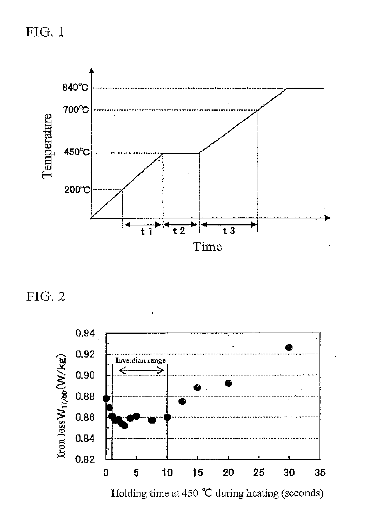
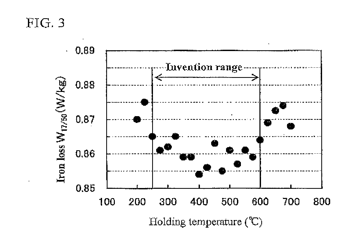
[0053]Thereafter, the cold rolled sheet is subjected to decarburization annealing in a wet atmosphere of 50 vol % H2-50 vol % N2 at 840° C. for 100 seconds. In this case, a heating rate in a zone of 200-700° C. during the heating process up to 850° C. is changed as shown in Table 1, while for the temperature and time shown in Table 1 holding on the way of the heating is performed.

[0054]Then, the st...

example 2

[0056]A steel slab having a chemical composition shown in Table 2 and comprising the remainder being Fe and inevitable impurities is manufactured by a continuous casting method, heated to a temperature of 1380° C. and hot rolled to obtain a hot rolled sheet of 2.0 mm in thickness. The hot rolled sheet is annealed at 1030° C. for 10 seconds and cold rolled to 0.23 mm. Thereafter, the cold rolled sheet is subjected to decarburization annealing combined with primary recrystallization annealing in a wet atmosphere of 50 vol % H2-50 vol % N2 at 840° C. for 60 seconds. In this case, a heating rate in a range of 200-700° C. during the heating process up to 840° C. is 75° C. / s, and a temperature of 450° C. is hold for 1.5 seconds on the way of the heating.

[0057]Then, the steel sheet is coated on its surface with an annealing separator composed mainly of MgO, dried and subjected to final annealing combined with a purification treatment at 1220° C. for 4 hours. The atmosphere of the final ann...


PUM

PropertyMeasurementUnit
temperatureaaaaaaaaaa

Abstract

In a method for producing a grain-oriented electrical steel sheet by including a series of steps of hot rolling a raw steel material containing C: 0.002-0.10 mass %, Si: 2.0-8.0 mass % and Mn: 0.005-1.0 mass % to obtain a hot rolled sheet, subjecting the hot rolled steel sheet after or without hot band annealing to one stage cold rolling or two or more stage cold rollings including an intermediate annealing therebetween to obtain a cold rolled sheet having a final sheet thickness, subjecting the cold rolled sheet to decarburization annealing combined with primary recrystallization annealing, applying an annealing separator to the steel sheet surface, and then subjecting to a final annealing.

Description

CROSS REFERENCE TO RELATED APPLICATION[0001]This application is a divisional application of U.S. application Ser. No. 14 / 415,089, filed Jan. 15, 2015, the contents of which are incorporated herein by reference.TECHNICAL FIELD[0002]This invention relates to a method for producing a grain-oriented electrical steel sheet, and more particularly to a method for producing a grain-oriented electrical steel sheet which is low in the iron loss and small in the magnetic property deviation.RELATED ART[0003]The electrical steel sheets are soft magnetic materials widely used as iron cores for transformers, motors or the like. Among them, the grain-oriented electrical steel sheets are excellent in the magnetic properties because their grain orientations are highly accumulated into {110}<001> orientation called as Goss orientation, so that they are mainly used as iron cores for large-size transformers or the like. In order to decrease no-load loss (energy loss) in the transformer, the iron l...

Claims


Application Information

Patent Timeline
Patent Type & Authority Applications(United States)
IPC IPC(8): C21D9/46C21D6/00C22C38/60C22C38/40C22C38/00C22C38/12C22C38/06C22C38/04C22C38/02C21D8/12C22C38/16
CPCC21D9/46C22C38/001C21D8/1272C21D8/1266C21D8/1261C21D8/1255C21D8/1233C21D8/1222C21D6/008C21D6/005C21D6/004C22C38/60C22C38/40C22C38/16C22C38/12C22C38/06C22C38/04C22C38/02C22C38/008C22C38/002C21D8/1283C21D8/12C21D2201/05C22C38/00C22C38/34H01F1/16Y02W30/50H01F1/14775
Inventor IMAMURA, TAKESHISHINGAKI, YUKIHIROWATANABE, MAKOTOSUEHIRO, RYUICHITAKAMIYA, TOSHITO
Owner JFE STEEL CORP
Why Eureka
Try Eureka