Fe-BASED AMORPHOUS ALLOY RIBBON, PRODUCTION METHOD THEREOF, IRON CORE, AND TRANSFORMER
a technology of amorphous alloy ribbon and a production method, which is applied in the direction of heat treatment apparatus, furnaces, magnetic bodies, etc., can solve the problems of load loss, and achieve the effects of low iron loss, less deformation, and high production efficiency
- Summary
- Abstract
- Description
- Claims
- Application Information
AI Technical Summary
Benefits of technology
Problems solved by technology
Method used
Image

Examples
example 1
[0284]
[0285]A material ribbon (namely, Fe-based amorphous alloy ribbon before laser processing) having a chemical composition of Fe82Si4Bi4 and having a thickness of 25 μm and a width of 210 mm was produced by a single roll method.
[0286]The “chemical composition of Fe82Si4Bi4” here means a chemical composition which consists of Fe, Si, B, and an impurity and in which the content of Fe is 82 atom %, the content of B is 14 atom %, and the content of Si is 4 atom % in a case in which the total content of Fe, Si, and B is 100 atom %.
[0287]Hereinafter, production of the material ribbon will be described in detail.
[0288]The material ribbon was produced by retaining a molten metal having a chemical composition of Fe82Si4Bi4, at a temperature of 1300° C., next ejecting the molten metal through a slit nozzle onto a surface of an axially rotating cooling roll, and rapidly solidifying the molten metal ejected, on the surface of the cooling roll.
[0289]The ambient atmosphere immediately under th...
example 2
[0376]
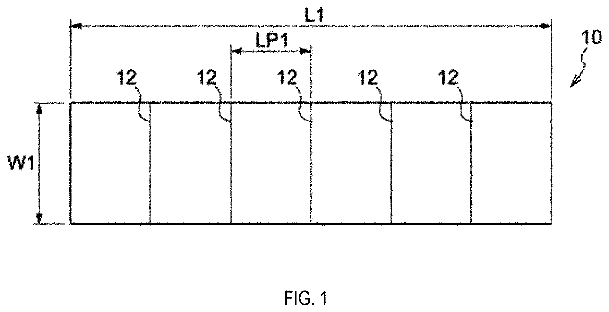
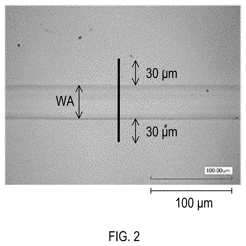
[0377]Linear laser irradiation marks were formed on a roll surface of a material ribbon, which is the same material ribbon as the material ribbon used in Example 1, at a line interval LP1 of 20 mm, a scanning speed of 5 m / sec, and a laser output energy density of 10 J / m. FIG. 32 shows an observation photo of the linear laser irradiation mark. The heat treatment conditions were the same as those used in Example 1.
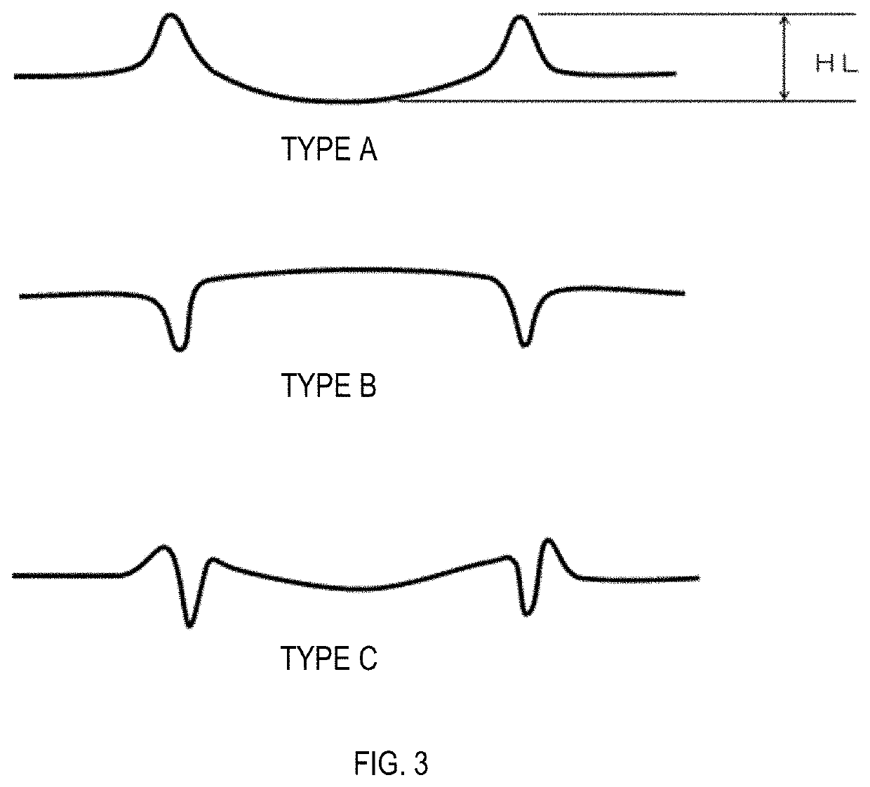
[0378]The height difference HL of Example 2 was 1.04 μm, the width WA was 38.56 μm, and the height difference HL×width WA was 40.10 μm2. The iron loss CL, the exciting power VA, and the coercive force Hc under the condition of a frequency of 60 Hz and a magnetic flux density of 1.45 T were respectively 0.0979 W / kg, 0.2413 VA / kg, and 2.0868 A / m, and the form of the linear laser irradiation marks and the characteristics obtained were the same as those of the Fe-based amorphous alloy ribbon of Example 1 in which the linear laser irradiation marks were formed on the free s...
example 3
[0379]An Fe-based amorphous alloy ribbon (chemical composition: Fe82Si4B14, thickness: 25 μm, width: 142 mm) was obtained in the same manner as in Example 1. Linear laser irradiation marks were formed at a line interval LP1 of 20 mm, a scanning speed of 8 m / sec, and a laser output energy density of 17 J / m, and Fe-based amorphous alloy ribbon pieces were prepared. Table 9 shows the state of the linear laser irradiation marks. In Example 3, the width WA was 70.5 μm, and the width WB was 0 μm. The unevenness of the linear laser irradiation mark on the laser irradiated surface A had a height difference HL of 0.44 μm, and a height difference HL×width WA of 31.02 μm2. No linear laser irradiation marks were observed on the back surface B of the laser irradiated surface A. No stress wrinkle was found.
[0380]Ribbon pieces obtained were layered to form a laminated body, the laminated body was bent into a U-shape and wound with both ends thereof being overlapped, thereby providing an iron core ...
PUM
| Property | Measurement | Unit |
|---|---|---|
| width WA | aaaaa | aaaaa |
| height | aaaaa | aaaaa |
| thickness | aaaaa | aaaaa |
Abstract
Description
Claims
Application Information
 - R&D
- Intellectual Property
- Life Sciences
- Materials
- Tech Scout
- Unparalleled Data Quality
- Higher Quality Content
- 60% Fewer Hallucinations
Browse by: Latest US Patents, China's latest patents, Technical Efficacy Thesaurus, Application Domain, Technology Topic, Popular Technical Reports.
© 2025 PatSnap. All rights reserved.Legal|Privacy policy|Modern Slavery Act Transparency Statement|Sitemap|About US| Contact US: help@patsnap.com