Eureka AIR delivers breakthrough ideas for toughest innovation challenges, trusted by R&D personnel around the world.

Fluid intake for an artificial lift system and method of operating such system

Active Publication Date: 2016-11-03
BAKER HUGHES OILFIELD OPERATIONS LLC
View PDF3 Cites 12 Cited by
  • Summary
  • Abstract
  • Description
  • Claims
  • Application Information

AI Technical Summary

Benefits of technology

The patent describes a system for drawing fluid from a well. The system includes a fluid intake with a support structure and a porous member that allows liquid to pass through. The intake is inserted into the well casing, and the pump is used to draw the fluid through the intake and into the interior space of the intake. The system also includes a connection line that connects the interior space to the pump inlet. The technical effect of this system is to provide an improved method for accessing and pumping fluid from a well.

Problems solved by technology

In at least some known wells, the flow of both liquid and gas phase materials through the wellbore results in unsteady flow regimes, i.e., the flow is not a constant stratified flow regime.
As a result, gas is drawn towards and ingested by the pump, which causes a reduction in the expected operational lifetime of the pump.
Additionally, the pump undergoes large load fluctuations when ingesting gas.
More specifically, the pump requires a relatively large amount of power to lift large volumes of liquid during standard operation.
When gas reaches the pump, the pump experiences a drop in power consumption because the pump is no longer doing as much work.
Subsequently, when liquid enters the pump again, the power consumption increases significantly over a relatively short period of time.
Such load fluctuations reduce pumping efficiency and further reduce the expected operational lifetime of the pump, the driver that operates the pump, and the power delivery system that supplies power to the pump.
Additionally, some known intakes are relatively short, causing higher fluid velocities normal to a surface of the intake.
The higher fluid velocities normal to the surface generate undesirable flow structures, such as vortices.
Additionally, the higher fluid velocities normal to the surface result in relatively high pressure drops at the surface.
The undesirable flow structures and high pressure drops cause gas to be drawn into the intakes and, as a result, cause the pump to operate less efficiently.

Method used


Image

  • Fluid intake for an artificial lift system and method of operating such system
  • Fluid intake for an artificial lift system and method of operating such system
  • Fluid intake for an artificial lift system and method of operating such system

Examples


Embodiment Construction

[0017]In the following specification and the claims, reference will be made to a number of terms, which shall be defined to have the following meanings.

[0018]The singular forms “a”, “an”, and “the” include plural references unless the context clearly dictates otherwise.

[0019]“Optional” or “optionally” means that the subsequently described event or circumstance may or may not occur, and that the description includes instances where the event occurs and instances where it does not.

[0020]Approximating language, as used herein throughout the specification and claims, may be applied to modify any quantitative representation that could permissibly vary without resulting in a change in the basic function to which it is related. Accordingly, a value modified by a term or terms, such as “about”, “approximately”, and “substantially”, are not to be limited to the precise value specified. In at least some instances, the approximating language may correspond to the precision of an instrument for...


PUM


Abstract

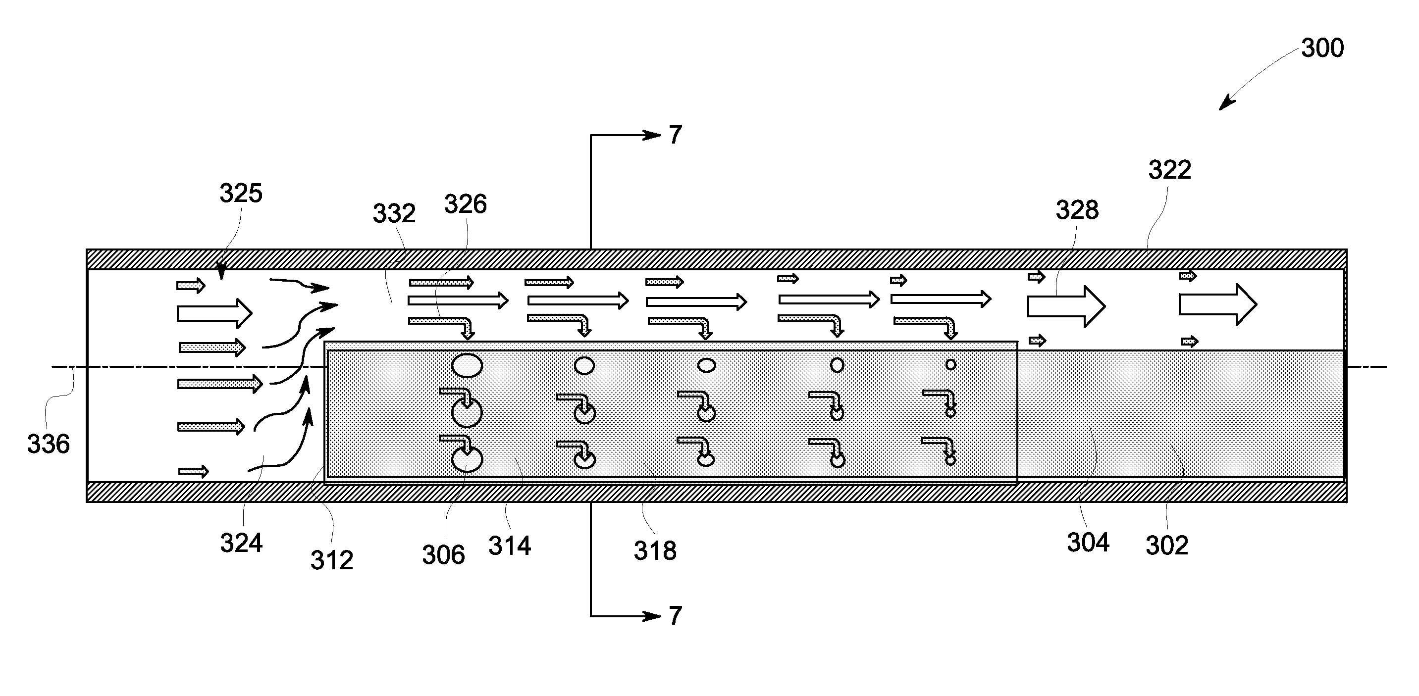
A fluid intake for a system includes a support structure defining an interior space and configured for fluid to pass into the interior space. The system includes a pump for pumping fluid from a well including a well casing defining a passageway for the fluid to flow therethrough in a flow direction. The fluid includes liquid and gas. A porous member extends over a portion of the support structure. The fluid intake extends inside the passageway in the flow direction such that the porous member and the well casing define an annular space therebetween. The porous member defines pores for liquid to wick through. The interior space is in flow communication with the pores such that liquid wicking through the porous member passes into the interior space.

Description

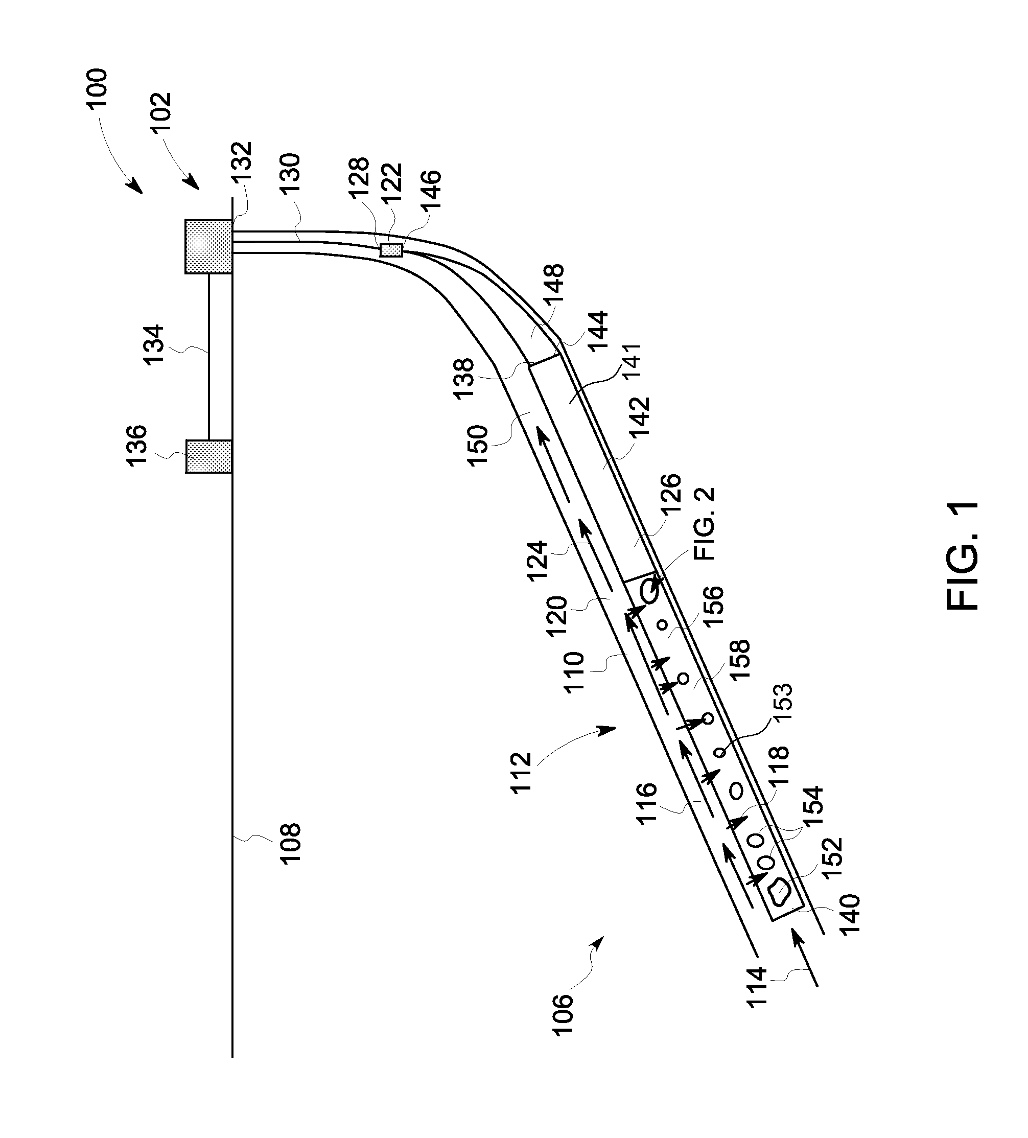
BACKGROUND[0001]The field of the disclosure relates generally to artificial lift systems for hydrocarbon producing wells and, more particularly, to a fluid intake for use in artificial lift systems for hydrocarbon producing wells.[0002]Typical hydrocarbon producing wells include a wellbore for transporting materials that are withdrawn from a hydrocarbon formation. The materials pass from the formation into the wellbore and are channeled along the wellbore to the wellhead. These materials consist of one or more of gaseous, liquid, or solid phase substances.[0003]Some wells utilize an artificial lift system to increase the production of materials from the wells. Artificial lifts systems typically include a pump that causes the materials to flow through the wellbore towards the wellhead. In at least some known wells, the flow of both liquid and gas phase materials through the wellbore results in unsteady flow regimes, i.e., the flow is not a constant stratified flow regime. As a result...

Claims


Application Information

Patent Timeline
IPC IPC(8): E21B43/38E21B43/12
CPCE21B43/38E21B43/121E21B43/35
Inventor REEVES, BRIAN PAULCOLLINS, CHARLES EVANACACIO, VICTOR JOSEZHANG, JINFENG
Owner BAKER HUGHES OILFIELD OPERATIONS LLC
Why Eureka
Eureka Blog
Learn More