Resection guides, implants and methods

Active Publication Date: 2016-11-10
ZIMMER INC
View PDF1 Cites 50 Cited by
  • Summary
  • Abstract
  • Description
  • Claims
  • Application Information

AI Technical Summary

Benefits of technology

[0007]In another aspect, provided herein is a surgical method for correcting a bone deformity including removing a piece of bone from a bone and aligning a guide on the bone over an area of bone where the piece of bone was removed. The method may also include inserting at least one temporary fixation device into an opening in the guide. In addition, the method may include drilling at least one opening into the bone through at least one drill opening in the guide. The method may further include removing the at least one temporary fixation device to remove the guide from the bone. The method may also include cutting the bone along the first cut line and at least one second cut line. Further, the method may include inserting at least one engagement portion of an implant into the at leas

Problems solved by technology

Bunions may become irritating and in some cases very painful during walking and other weight bearing activities.
The cuts of the Reverdin osteotomy are typically made free hand without guides, thus surgeons are unable to preplan and exec

Method used


Image

  • Resection guides, implants and methods
  • Resection guides, implants and methods
  • Resection guides, implants and methods

Examples


embodiment 300

[0103]Referring now to FIGS. 15-20, another guide embodiment 300 is shown. The guide 300 may include a plate 302 and a guide body 304 extending out from the plate 302. The plate 302 may include a first end 318 and a second end 320. The plate 302 may also include at least one aperture 306 for inserting at least one temporary fixation device (not shown) and a notch 308. In addition, the plate 302 may include openings 310 near the second end 320 of the plate 302 and extending through the guide body 304. The plate 302 may further include a first reference surface 312, a second reference surface 314, and a third reference surface 316 extending from the plate 302 into and through the guide body 304.

[0104]As shown in FIGS. 18 and 19, the first reference surface 312 may extend from a position near the notch 308 to a position near the openings 310. The notch 308 and the first reference surface 312 may be aligned. The first reference surface 312 may also be angled relative to the longitudinal...

embodiment 500

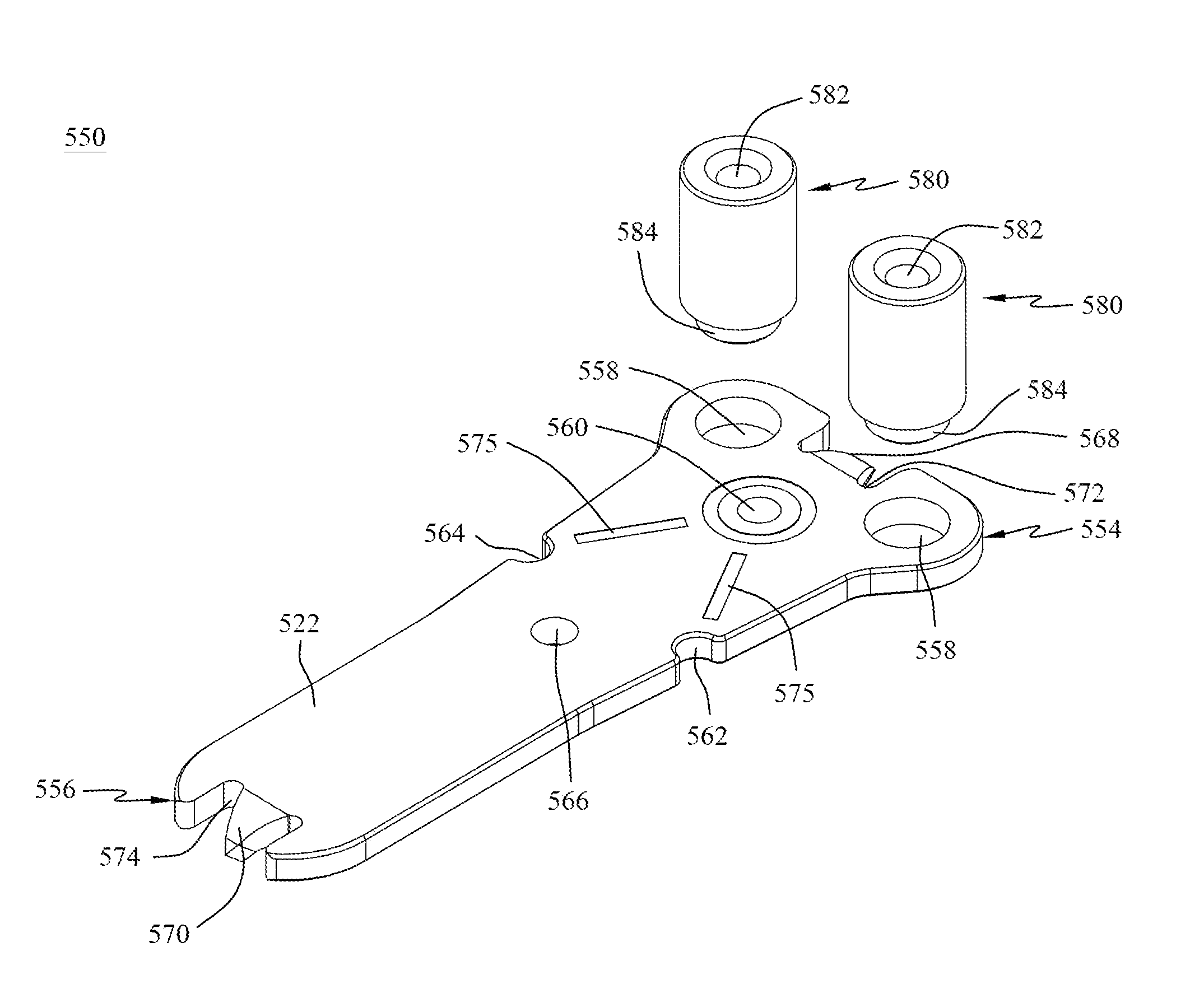
[0107]Another guide embodiment 500 is shown in FIGS. 22A-22F and 27-30. The guide 500 may include a plate 502 with a first end 504 and a second end 506. The first end 504 may be a distal end of the plate 502 and the second end 506 may be a proximal end of the plate 502. The plate 502 may further include a medial portion extending between the first end 504 and the second end 506. The guide 500 may be, for example, tapered from the first end 504 to the second end 506 along its length. The first end 504 of the guide 500 may have a width, for example, greater than the width of the second end 506.

[0108]The guide 500 may also include at least one opening 508. In the depicted embodiment there are two openings 508, near the first end 504. The at least one opening 508 may be, for example, surrounded by screw sleeves or bushings 509 extending out from the plate 502 near the first end 504. The screw sleeves 509 may be integral with the plate 502 or removable from the plate 502 to allow for mod...


PUM


Abstract

Resection guides, implants and methods are disclosed. A guide may include a plate with a first end opposite a second end and a medial portion extending therebetween. The guide may also include at least one opening in the first end of the plate. The guide may further include at least one hole positioned along a longitudinal axis of the plate near the at least one opening. Surgical methods for using the guide for bone and joint fusions is also disclosed.

Description

CROSS REFERENCE TO RELATED APPLICATION[0001]This application claims priority benefit to U.S. provisional application No. 61 / 924,296 filed Jan. 7, 2014, which is incorporated herein by reference in its entirety.FIELD OF THE INVENTION[0002]The present invention relates generally to general surgery, and more particularly to orthopedic surgery. More specifically, but not exclusively, the present invention concerns guides and implants used during surgery for resecting a bone.BACKGROUND OF THE INVENTION[0003]One such type of bone resection is bunion deformities which are generally found on a person's foot, more specifically they are found on a person's toes. A bunion deformity or hallux abducto valgus deformity results from the big toe deviating laterally toward the patient's smallest toe. Due to the lateral movement of the big toe, the first metatarsal bone angles toward the smaller toes on the patient's foot causing the first metatarsal bone to move out of alignment. Bunions may become ...

Claims


Application Information

Patent Timeline
IPC IPC(8): A61B17/17A61B17/80A61B17/15
CPCA61B17/1728A61B2017/1775A61B17/809A61B17/15A61B17/151A61B17/8057A61B17/8061A61B2017/565A61B17/1775
Inventor MONTOYA, JORGE A.PEPPER, JOHN R.WEINER, LON S.KATCHIS, STUART D.
Owner ZIMMER INC
Why Eureka
Try Eureka