Humeral implant anchor system

a technology of humeral implants and anchor systems, which is applied in the field of stemless stemmed humeral components of shoulder joint prosthesis, can solve the problems of reducing the safety of implants, difficult to remove humeral components, and disadvantageous insertion of stems, and achieve excellent long-term fixation. , the effect of enhancing the initial pull-out resistan

Active Publication Date: 2016-11-10
HOWMEDICA OSTEONICS CORP
View PDF6 Cites 57 Cited by
  • Summary
  • Abstract
  • Description
  • Claims
  • Application Information

AI Technical Summary

Benefits of technology

[0009]Accordingly, there is a need for a stemless humeral component or prosthesis designed to preserve bone in initial implantation while enhancing initial pull-out resistance. Preferably enhanced initial dislodgement resistance will also provide excellent long term fixation.

Problems solved by technology

In certain cases, insertion of the stem disadvantageously requires bone to be removed to fit the stem to the canal due to patient-to-patient anatomical variation.
Another disadvantage of this approach is that integration of the stem into the bone through a natural process of bone ingrowth can make it difficult to remove the humeral component if it becomes necessary to replace the humeral component with another device.
Even when no removal was expected, this approach had the disadvantage of only achieving implant security after sufficient time had passed to allow for sufficient bone ingrowth.
Stemless humeral component designs can be more challenging to secure to the humerus.
While such designs perform well over time, there is a risk in the early days and weeks after surgery where such ingrowth has not yet occurred that the stem and stemless humeral component will be dislodged from the humerus.
Dislodgement may also occur due to excessive wear, forces applied thereto during a revision surgery or other high load conditions.

Method used


Image

  • Humeral implant anchor system
  • Humeral implant anchor system
  • Humeral implant anchor system

Examples


Embodiment Construction

[0061]While the present description sets forth specific details of various embodiments, it will be appreciated that the description is illustrative only and should not be construed in any way as limiting. Furthermore, various applications of such embodiments and modifications thereto, which may occur to those who are skilled in the art, are also encompassed by the general concepts described herein. Each and every feature described herein, and each and every combination of two or more of such features, is included within the scope of the present invention provided that the features included in such a combination are not mutually inconsistent.

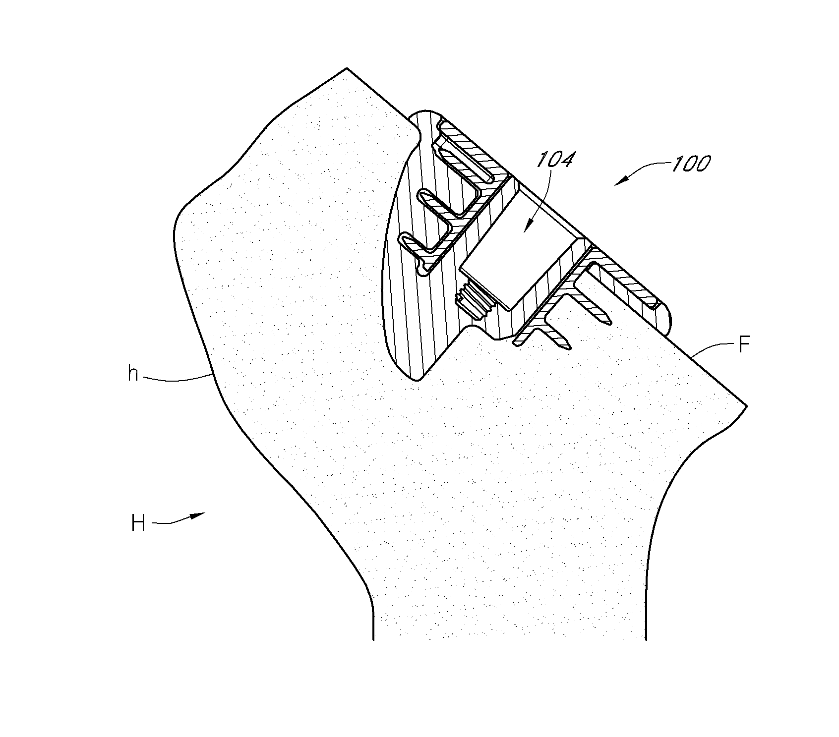
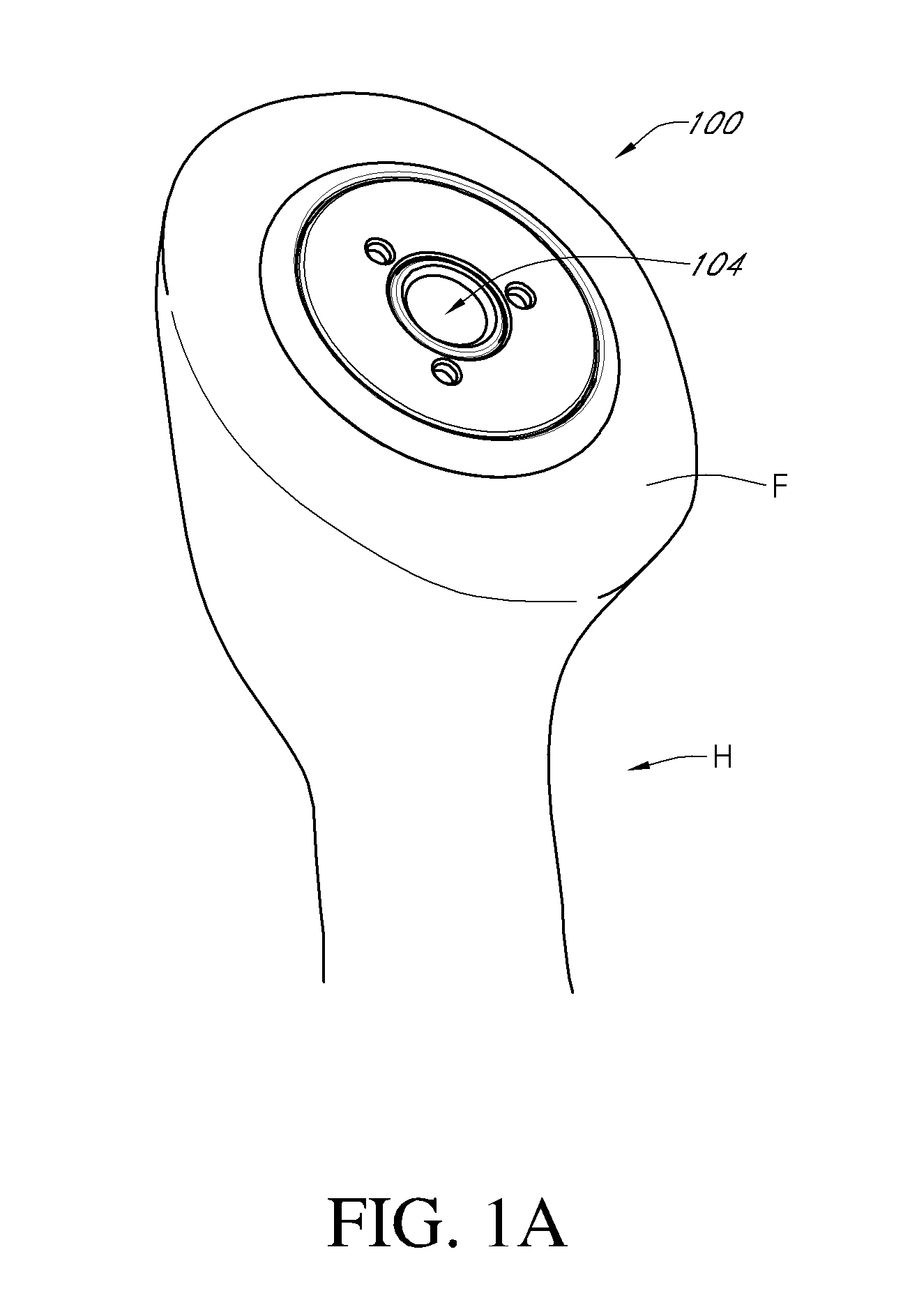
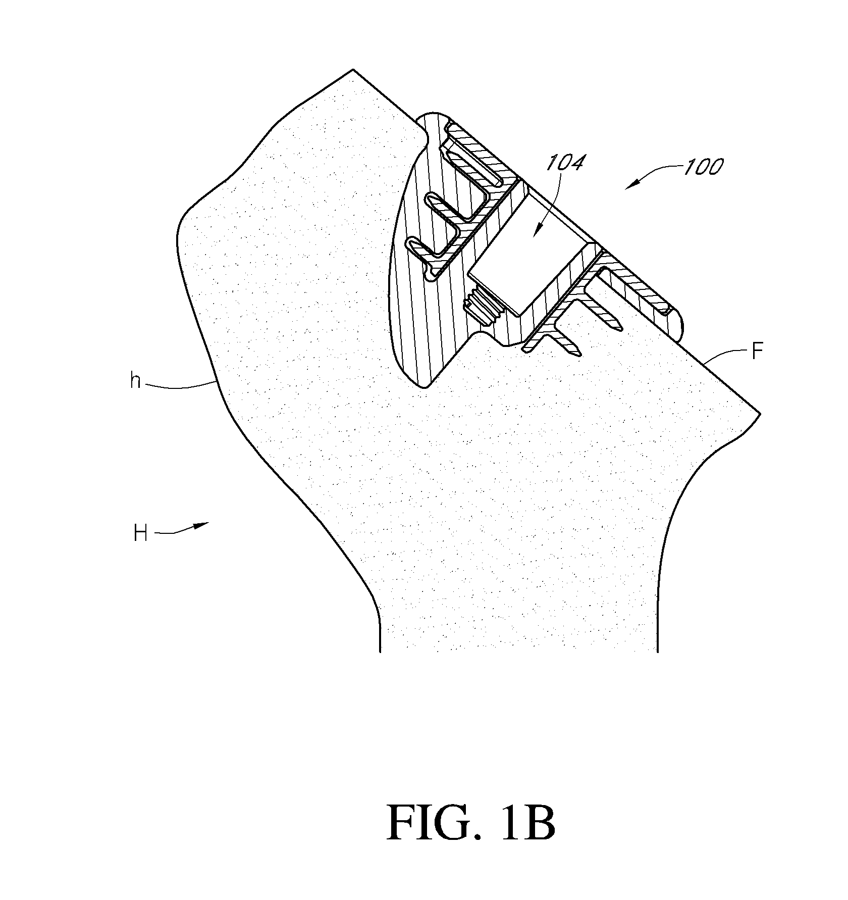
[0062]FIG. 1A shows a humeral shoulder assembly 100 that has been implanted in an exposed face F of a humerus H. The assembly 100 has a recess 104 in which further components of a prosthetic shoulder joint can be secured. The configuration of the assembly including the recess 104 enable the humerus H and a corresponding scapula to be fitted with ...


PUM


Abstract

A stemless humeral shoulder assembly having a base member and an anchor advanceable into the base member. The base member can include a distal end that can be embedded in bone and a proximal end that can be disposed at a bone surface. The base member can also have a plurality of spaced apart arms projecting from the proximal end to the distal end. The anchor can project circumferentially into the arms and into a space between the arms. When the anchor is advanced into the base member, the anchor can be exposed between the arms. A recess can project distally from a proximal end of the anchor to within the base member. The recess can receive a mounting member of an anatomical or reverse joint interface.

Description

CROSS-REFERENCE TO RELATED APPLICATIONS[0001]The present application is a continuation-in-part of PCT Application No. PCT / US2014 / 072443, filed Dec. 26, 2014, which claims to the priority benefit of U.S. Provisional Application No. 61 / 931,500, filed Jan. 24, 2014, both of which are hereby incorporated by reference in their entirety herein. The present application also claims the priority benefit of U.S. Provisional Application No. 62 / 192,797, filed Jul. 15, 2015, which is hereby incorporated by reference in its entirety herein.BACKGROUND[0002]1. Field[0003]The present disclosure relates to stemmed and stemless humeral components of a shoulder joint prosthesis.[0004]2. Description of the Related Art[0005]In a shoulder joint, the head of the humerus interacts with the glenoid cavity of the scapula in a manner similar to a “ball and socket” joint. Over time, it may become necessary to replace the shoulder joint with a prosthetic shoulder joint including a humeral component.[0006]Traditi...

Claims


Application Information

Patent Timeline
Patent Type & Authority Applications(United States)
IPC IPC(8): A61F2/40
CPCA61F2/4014A61F2/3094A61F2220/0008A61F2002/4018A61F2/4003A61F2/4059A61F2/4612A61F2/4637A61F2002/30289A61F2002/30405A61F2002/30408A61F2002/4007A61F2002/4062A61F2002/4074A61B17/1778A61B17/1684
Inventor HODOREK, BRIAN C.KNOX, KEVIN P.EDWARDS, THOMAS BRADLEY
Owner HOWMEDICA OSTEONICS CORP
Why Eureka
Try Eureka