
Method of estimation of the speed of an aircraft relative to the surrounding air, and associated system

a technology of aircraft speed and airframe, applied in navigation instruments, instruments, transportation and packaging, etc., can solve problems such as failure detection based on hardware redundancy of sensors of the same design, failure detection of common-mode faults, and failure to isolate failed sensors, so as to improve the tolerance of motion

Active Publication Date: 2016-11-10
THALES SA
View PDF0 Cites 8 Cited by
  • Summary
  • Abstract
  • Description
  • Claims
  • Application Information

AI Technical Summary

Benefits of technology

The invention proposes a method for estimating the speed of an aircraft relative to the surrounding air, the angle of attack of the aircraft, and the angle of sideslip of the aircraft without using sensors. The method uses measurements of the static pressure and temperature of the surrounding air, and integrates these measurements over a vertical path of the aircraft. The method also takes into account the effect of wind turbulence and the motion of the aircraft relative to the ground. The method offers better tolerance to failure modes and is simpler than other methods.

Problems solved by technology

Failure detection based on hardware redundancy of sensors of the same design does not make it possible to detect common-mode faults, i.e. a phenomenon capable of simultaneously affecting the proper operation of several sensors.
If a fault mode can affect at least half the sensors, then the isolation of the failed sensors is no longer possible.
Consequently, such an observer cannot discern a failure of the sensor leading to an error in the speed of the aircraft relative to the surrounding air that is lower than the amplitude of the speed of the surrounding air relative to the ground that would be developed by a strong gust of wind.
Access to this information is not easy.
It is possible to identify it in flight (by estimation techniques, explicitly or implicitly) but this operation generally turns out to be tricky.
The basic problem is the stabilization of the estimator so that the estimated measurement provides a faithful replica of reality, without directly using the measurement of the actual sensor, for fear that in case of failure of the sensor, the measurements provided by other sensors (presumed to be reliable) may not stabilize.
The estimator of the speed of an aircraft relative to the surrounding air, with kinematic coupling, with inertial measurements (cf J. C. Deckert et al, 1976, “F-8 aircraft sensor failure identification using analytical redundancy”, IEEE) operates in open-loop and its performance is limited by the uncertainty in the acceleration of the air relative to the ground.
The problem is then to ascertain with sufficient accuracy the characteristic data of the aircraft (aerodynamic coefficients, moments of inertia, thrust of the engines, mass) which come into the motion propagation equations.
These techniques induce heavy operational constraints.
In this case the formal validation of the performance of the observer is difficult since the analytical tie with the physics of the problem, which would have made it possible to reduce a priori the quantity of test cases to be passed in order to demonstrate the missing detection and false alarm rates, is lost.

Method used


Image

  • Method of estimation of the speed of an aircraft relative to the surrounding air, and associated system
  • Method of estimation of the speed of an aircraft relative to the surrounding air, and associated system
  • Method of estimation of the speed of an aircraft relative to the surrounding air, and associated system

Examples


Embodiment Construction

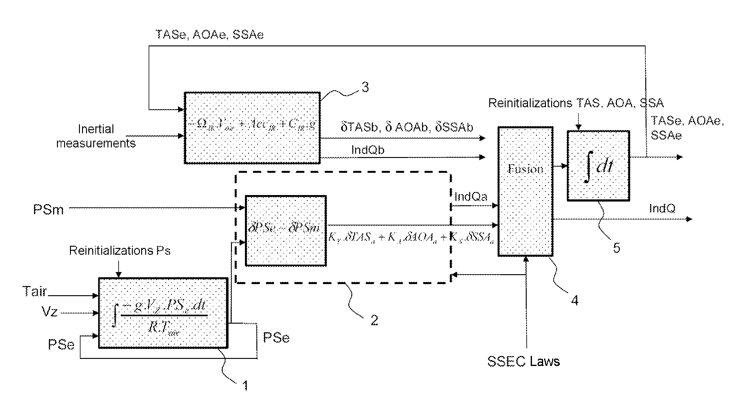
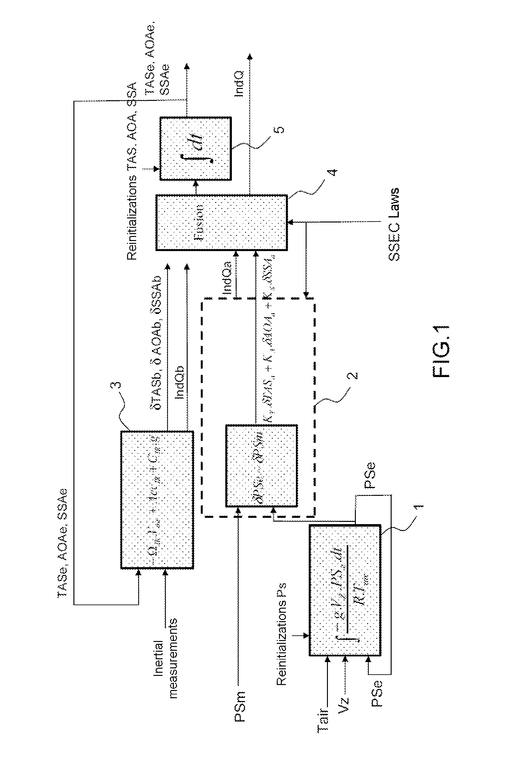
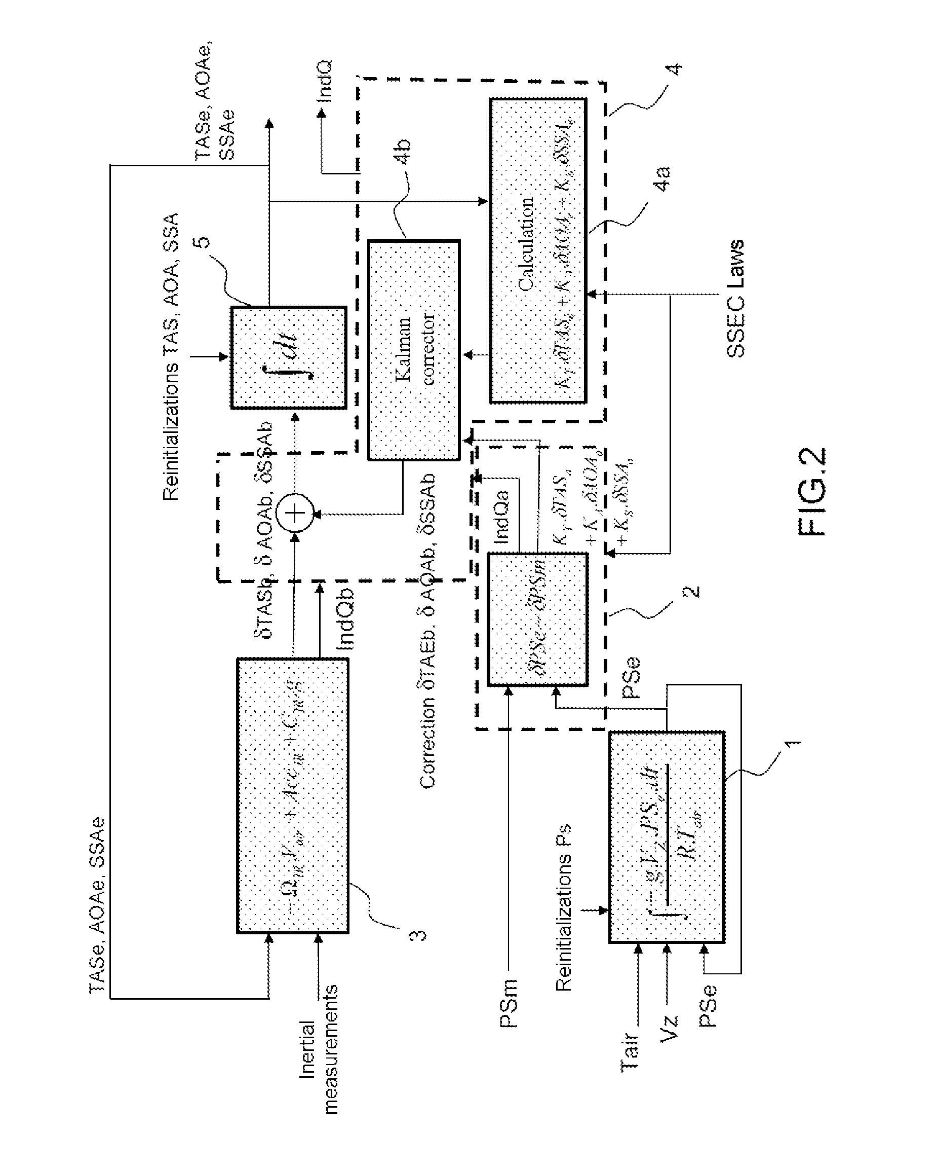
[0052]The method of estimation of the speed of an aircraft relative to the surrounding air, of the angle of attack of the aircraft, and of the angle of sideslip of the aircraft, in a reference frame tied to the aircraft, comprises:[0053]a first step 1 consisting in estimating an estimated static pressure PSe on the basis of measurements of the geographical vertical speed Vzgeo of the aircraft, of measurements of the temperature Tair of the surrounding air, of reinitializations of the estimated static pressure PSe, and of a feedback of the said estimated static pressure PSe, by integration over a vertical path of a hydrostatic equation;[0054]a second step 2 consisting in estimating a linear combination of a first intermediate variation δTASa of the speed of the aircraft relative to the surrounding air, of a first intermediate variation δAOAa of the angle of attack of the aircraft and of a first intermediate variation δSSAa of the angle of sideslip of the aircraft on the basis:[0055]o...


PUM


Abstract

Estimating the speed of an aircraft estimates three components of the speed vector (TAS, AOA, SSA) of an aircraft relative to the surrounding air. The static pressure is estimated on the basis of measurements of geographical altitude. A first intermediate variation of a linear combination of the three components of the speed vector of the aircraft relative to the surrounding air is estimated using explicitly the fact that the pressure measured by the static probe is falsified by a known quantity under the effect of the three components of this speed vector of the aircraft relative to the surrounding air. The process then estimates the three components of the speed vector of the aircraft relative to the air by likening the latter to the speed vector of the aircraft relative to an inertial reference frame and by using inertial measurements. The various estimates are fused to provide a final result.

Description

TECHNICAL FIELD[0001]The present invention pertains to a method of estimation of the speed of an aircraft relative to the surrounding air, in a reference frame tied to the aircraft.BACKGROUND OF THE INVENTION[0002]The piloting and guidance of an aircraft requires, among other information, knowledge of the speed vector of the aircraft relative to the surrounding air, and knowledge of the barometric altitude.[0003]This knowledge of the speed vector of the aircraft relative to the air is obtained on the basis of a set of probes which provide local measurements of pressure, of orientation of the air stream and of the temperature of the environment air, and which constitute input parameters for determining the speed vector of the aircraft relative to the air and the barometric altitude. This determination implements local aerodynamic corrections (SSEC laws, the acronym standing for “Static Source Error Correction”), which convey the matrix coupling between the local measurements and the ...

Claims


Application Information

Patent Timeline
Patent Type & Authority Applications(United States)
IPC IPC(8): B64D43/02G01C23/00G01S19/13
CPCB64D43/02G01C23/005G01S19/13G01P5/16G01P13/025G01P21/025
Inventor MEHLEN, CHRISTIANCOATANTIEC, JACQUES
Owner THALES SA
Learn More