
System and method for vaporizing fluids by combustion

a technology of vaporizing fluid and combustion chamber, which is applied in the field of hand-held vaporizers or micro-vaporizers, can solve the problems of frequent battery replacement, heavy weight of vaporizers, and frequent change of batteries, so as to avoid overheating

Active Publication Date: 2016-11-17
WESTFIELD GROUP
View PDF4 Cites 40 Cited by
  • Summary
  • Abstract
  • Description
  • Claims
  • Application Information

AI Technical Summary

Benefits of technology

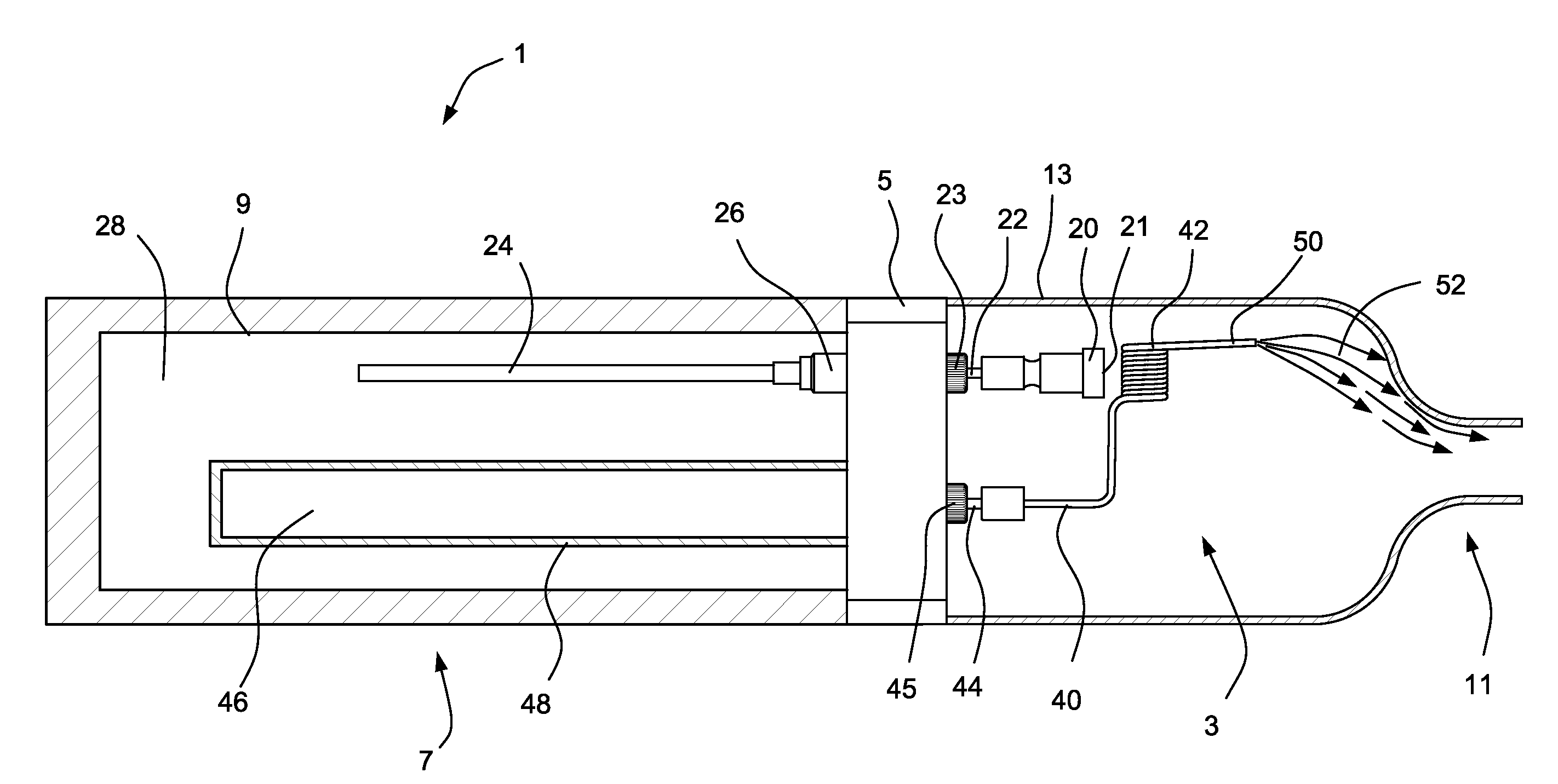
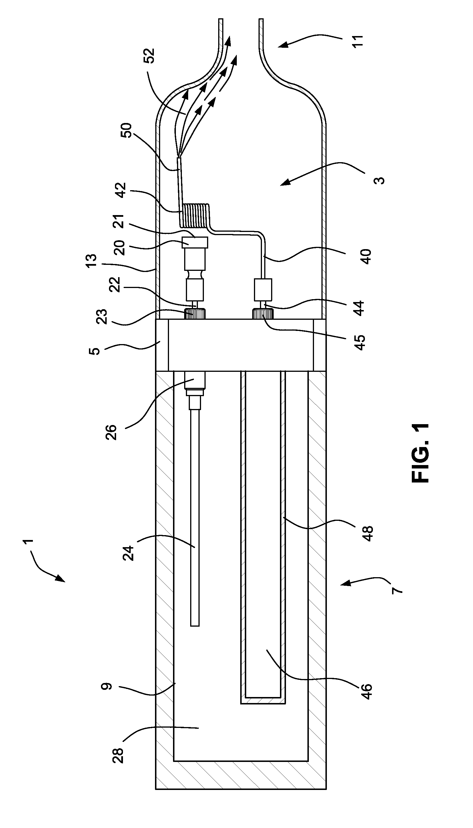
The patent describes a method of vaporizing liquids using heat from combustion. This method provides consistent heating and allows for quick heating, as well as quick shutting off of the heat source to avoid overheating and ensures safety. The technical effects of this method are more efficient and safe vaporization of liquids.

Problems solved by technology

To provide the vaporizer the ability of receiving, storing, and transforming electrical energy into heat energy for vaporization, the vaporizers are often bulky or heavy to carry.
If using disposable battery, the vaporizers also tend to require frequent changes to the battery; or if the battery were rechargeable, it would require frequent charges to the battery.

Method used


Image

  • System and method for vaporizing fluids by combustion
  • System and method for vaporizing fluids by combustion
  • System and method for vaporizing fluids by combustion

Examples


embodiment 600

[0049]The embodiment 600 may be a single manufactured cartridge that is fully disposable, or may be partially disposable by replacing or refilling the collapsible container 605 with new stored fluid 607.

[0050]FIG. 7 shows a sixth embodiment that provides stored fluid 707 to a combustion heating device 730. The embodiment 700 includes an outer casing 701, which defines a vaporization chamber 742 that is connected to a mouthpiece 740 on one end of the vaporization chamber 742, which is open to the atmosphere. The outer casing 701 includes an air hole 718 on a second end of the vaporization chamber 742 that allows air 722 to be drawn into the vaporization chamber 742.

[0051]The outer casing 701 also forms a support 716 that engages with a fluid transport device, such as a wick 714, which supplies stored fluid 707 to the vaporization section 742 to be vaporized by the combustion heating device 730. The wick 714 fluidly communicates between the vaporization section 742 and a container 705...

embodiment 700

[0055]The embodiment 700 may be a single manufactured cartridge that is fully disposable, or may be partially disposable by replacing or refilling the container 705 with new stored fluid 707.

[0056]The use of vaporization through combustion heating can be applied to another embodiment vaporizer in the shape of a pipe as shown in FIG. 8. The pipe 800 is formed by an outer casing 801 that includes a mouthpiece 840, using which a user would draw vaporized fluid 824 from the pipe 800. The pipe 800 also includes a top opening 803 that may be covered by a lid 805. Combustion fluid and stored liquid for vaporization are encased inside the pipe 800, and as can be seen through the top opening 803, the stored liquid may be transported to a combustion heating device 830 using a fluid transport device 814 in the shape of a pipe that allows fluid to be vaporized inside the pipe, and returns the vaporized fluid 824 to exit towards the mouthpiece 840. The fluid transportation device 814 may be any ...


PUM


Abstract

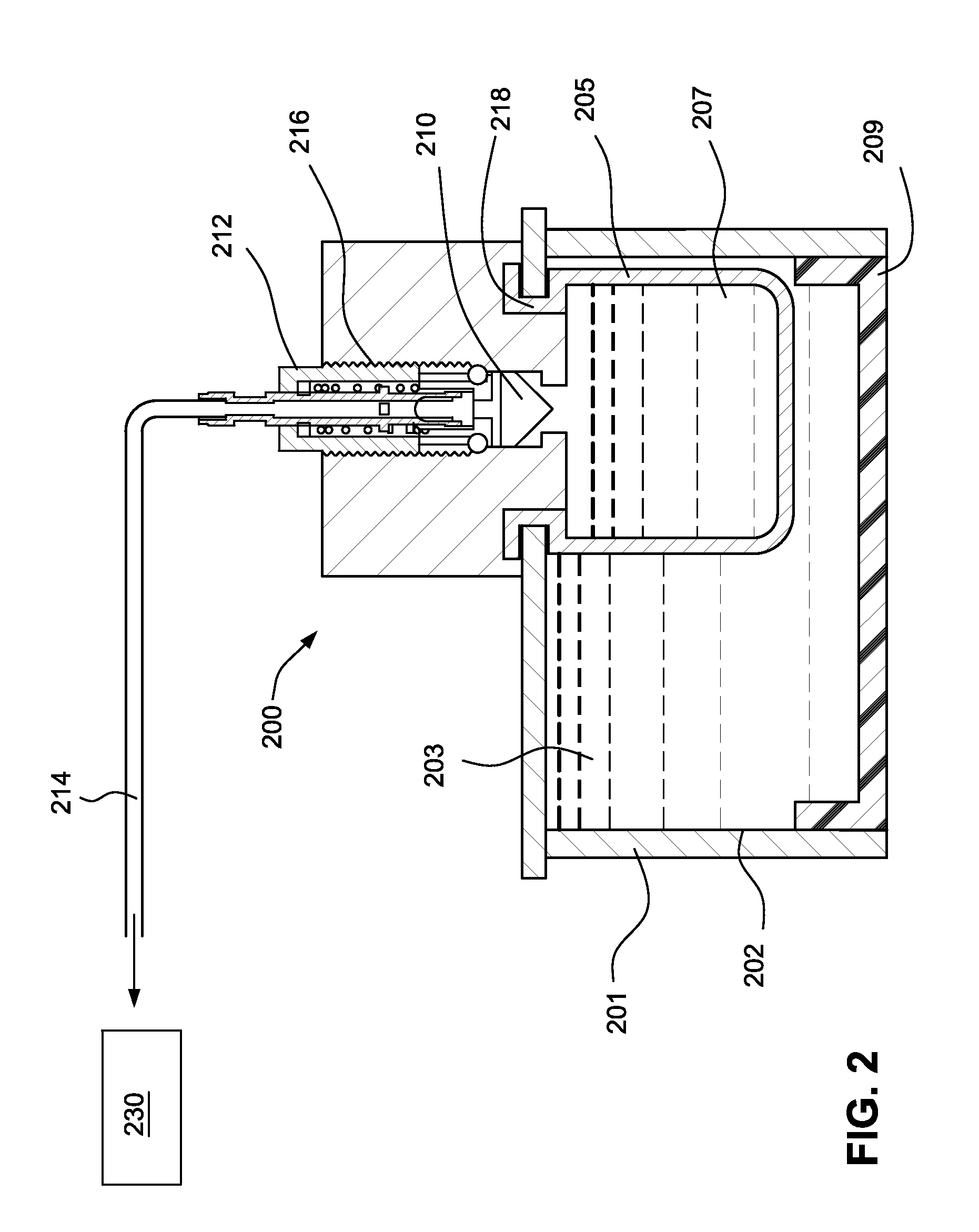
A microvaporizer having a combustion heating device to vaporize stored fluids to produce vapors, including methods to supply fluid to the combustion heating device by pressure induced by a switch that releases pressure, a spring, or a negative pressure induced by a user's sucking action on a mouthpiece of the microvaporizer.

Description

BACKGROUND OF THE INVENTION[0001]The present invention relates to a handheld vaporizer or microvaporizer, particularly the vaporizer uses combustion to vaporize fluids to produce vapor.[0002]The conventional handheld vaporizers or microvaporizers used as electronic cigarettes or electronic cigars are powered by electricity, through the forms of batteries or by plugging the vaporizer to an electrical outlet. To provide the vaporizer the ability of receiving, storing, and transforming electrical energy into heat energy for vaporization, the vaporizers are often bulky or heavy to carry. If using disposable battery, the vaporizers also tend to require frequent changes to the battery; or if the battery were rechargeable, it would require frequent charges to the battery.BRIEF SUMMARY OF THE INVENTION[0003]The present invention provides an alternative to the electrically powered handheld vaporizers or microvaporizers by using combustion, instead of electricity, to produce vapors.[0004]Heat...

Claims


Application Information

Patent Timeline
Patent Type & Authority Applications(United States)
IPC IPC(8): A24F47/00A24F42/10A24F42/60
CPCA24F47/006A24F42/10A24F42/60
Inventor XU, YONGJIE JAMES
Owner WESTFIELD GROUP
Learn More