Footwear

a technology for footwear and soles, applied in the field of footwear, can solve the problems of stopper claws, insufficient strength to prevent detachment, and the mechanism cannot be applied to footwear having a small thickness

Active Publication Date: 2016-11-17
WEDGE COOL LTD
View PDF1 Cites 10 Cited by
  • Summary
  • Abstract
  • Description
  • Claims
  • Application Information

AI Technical Summary

Benefits of technology

[0008]The present invention provides a footwear capable of sufficiently preventing the detachably attached upper portion from being detached although the thickness of the footwear can be kept smaller.
[0035]a dimension of each of the insertion holes is specified so that the insertion pieces can be inserted into the insertion holes after when the insertion pieces becomes smaller in width by being in contacted with the insertion holes and pushed by the insertion holes from both lateral ends of the insertion pieces to shrink the locking hole.

Problems solved by technology

However, only the stopper claws (21 or 25A) disclosed in Patent Document 1 are not strong enough for preventing the detachment.
Thus, the mechanism could not be applied to a footwear having a small thickness.

Method used


Image

  • Footwear
  • Footwear
  • Footwear

Examples


first embodiment

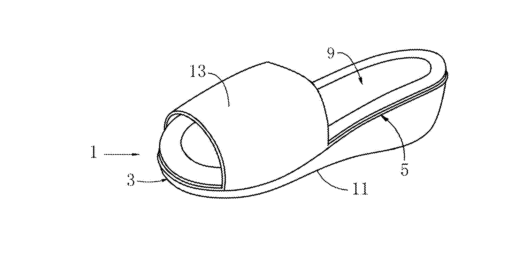
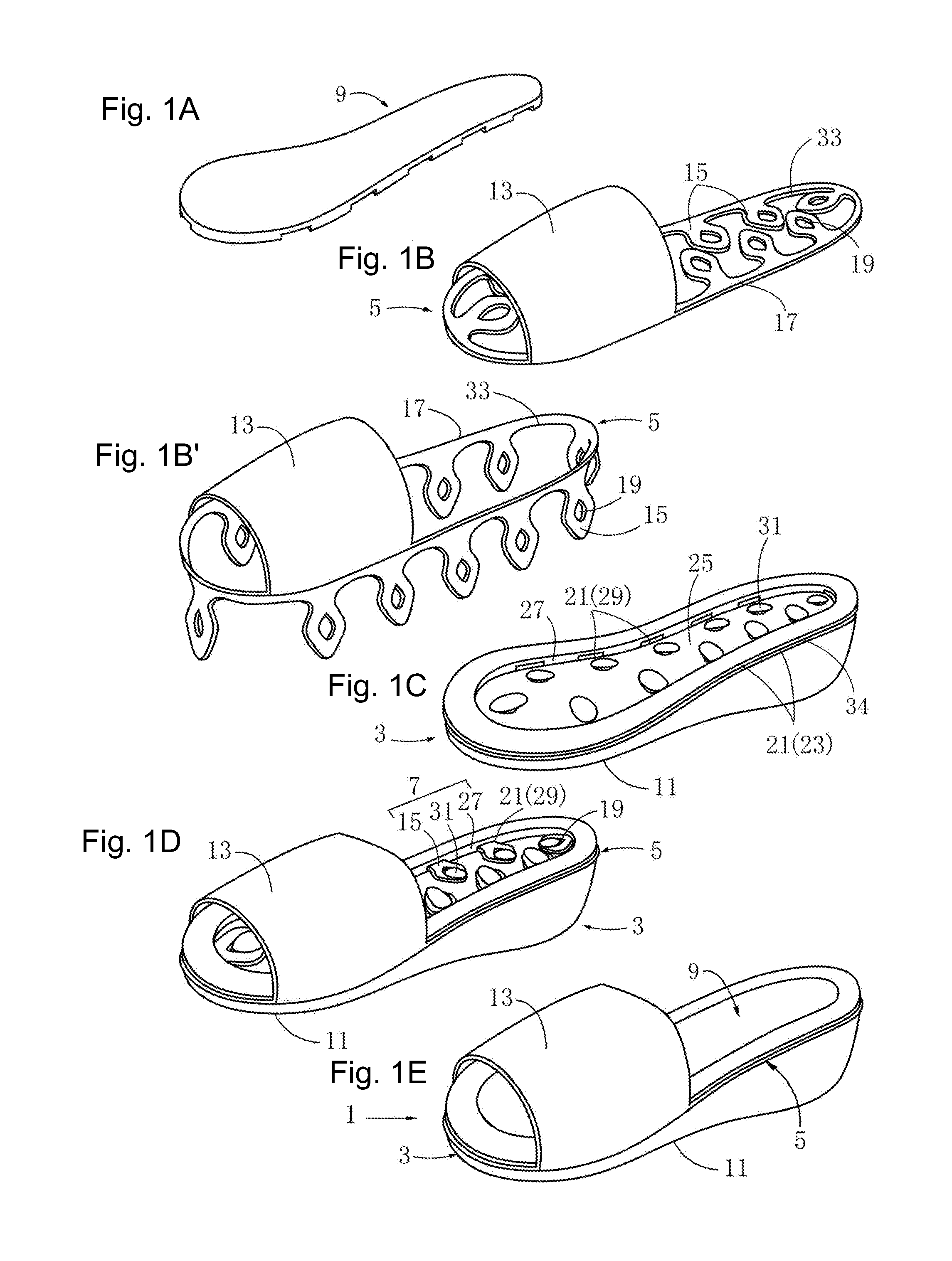
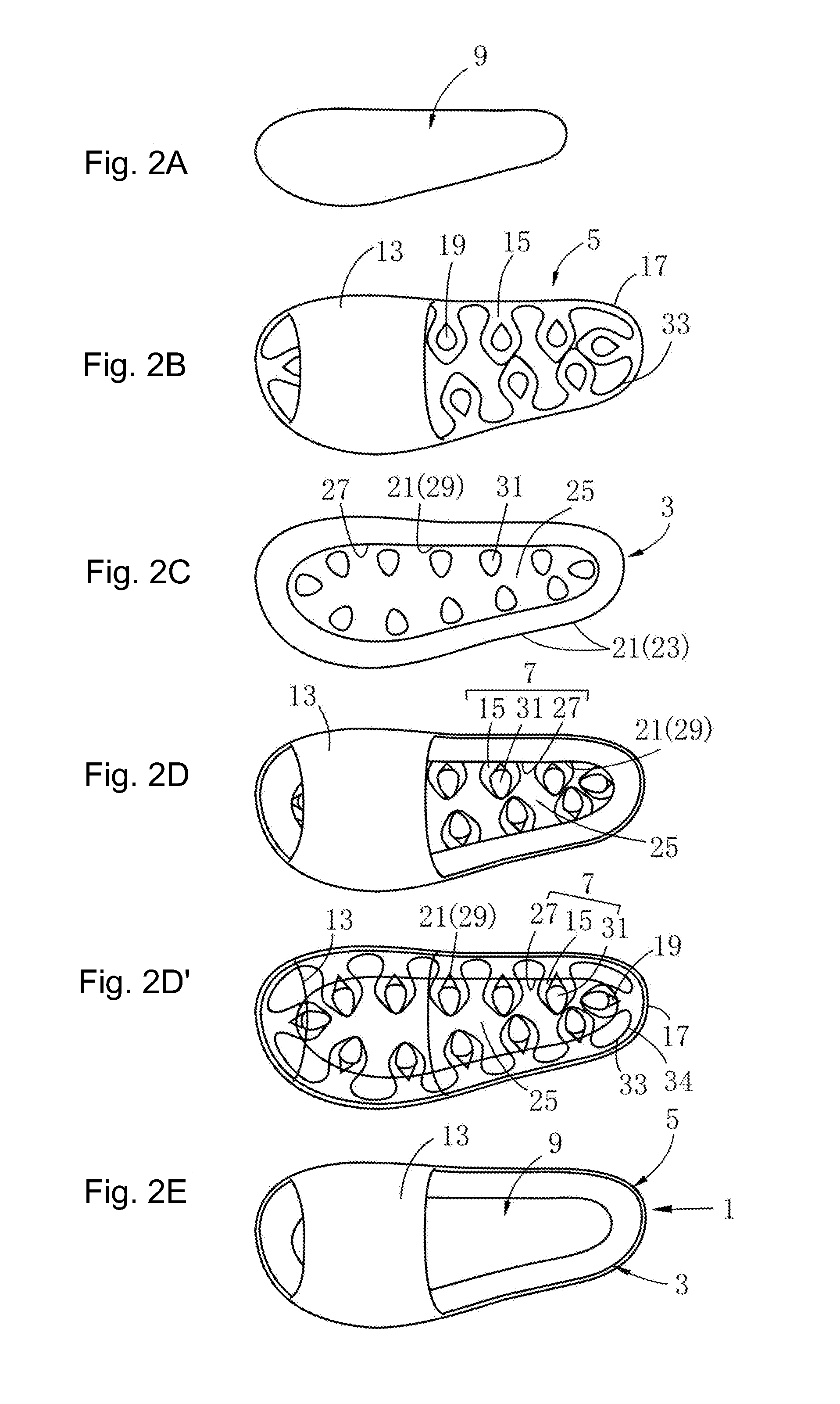
[0077]As shown in FIGS. 1A to 1E, 1D′, 2A to 2E and 2D′, a footwear 1 of the first embodiment is a sandal. An upper portion 5 is detachably attached to an outsole portion 3 and then a detachable mechanism 7 is covered with an insole portion 9. Thus, the upper portion 5 is replaceable.

[0078]As shown in FIG. 1C, the outsole portion 3 forms a lower portion of the footwear 1, and the outsole portion 3 has a portion 11 to be in contact with the ground.

[0079]As shown in FIG. 1B and FIG. 2B, the upper portion 5 can be attached to and detached from the outsole portion 3, and the upper portion 5 has a portion 13 crossing over instep of foot. For attaching and detaching the upper portion 5, a plurality of insertion pieces 15 is formed on an entire periphery of the upper portion 5.

[0080]The insertion pieces 15 are integrally formed with the upper portion 5 by the same material having strength and elasticity. For example, synthetic resin is used. A locking hole 19 is formed at an approximately ...

fifth embodiment

[0090]FIGS. 5A to 5E and 5A′ to 5E′ show a footwear of the present invention.

[0091]The footwear 1 of the fifth embodiment is a sandal. An upper portion 5 is detachably attached to an outsole portion 3 and covered with an insole portion 9. Thus, the upper portion 5 can be replaced.

[0092]As shown in FIGS. 5C and 5C′, the outsole portion 3 forms a lower part of the footwear 1, and the outsole portion 3 has a portion 11 to be in contact with the ground.

[0093]As shown in FIGS. 5B and 5B′, the upper portion 5 can be attached to and detached from the outsole portion 3, and the upper portion 5 has a portion 13 crossing over instep of foot. For attaching and detaching the upper portion 5, a plurality of insertion pieces 15 is formed on an entire periphery of the upper portion 5.

[0094]The insertion pieces 15 are integrally formed with the upper portion 5 by the same material having strength and elasticity. For example, synthetic resin is used. The insertion pieces 15 are formed on a periphery...

sixth embodiment

[0102]In the sixth embodiment, different from other embodiments, after the insertion pieces 15 are inserted into the insertion holes 21 and reached to the recess 25 formed at the center, locking claws 41 are locked by lock receiving portions 45 arranged at the bottom of the recess 25. A shape of the lock receiving portions 45 is inclined upward in a slope shape toward a front side in the insertion direction. Because of this, the lock receiving portions 45 do not interfere with the insertion of the insertion pieces 15, and the insertion pieces 15 can be smoothly attached and detached. A fit-in port of the lock receiving portions 45 is narrower than a dimension of the corresponding part of the locking claws 41 and a tip of the lock receiving portions 45 is projected (FIG. 6E″) toward the insertion direction. Because of this, the locking claws 41 are prevented from being removed from the lock receiving portions 45.

[0103]Accordingly, same as the first embodiment, the insertion pieces ar...


PUM

PropertyMeasurementUnit
elasticityaaaaaaaaaa
shapeaaaaaaaaaa
widthaaaaaaaaaa

Abstract

An upper portion of a footwear is detachably attached, the attached upper portion is sufficiently prevented from being removed, and the footwear can be thinner. To attach an upper portion (5) on an outsole portion (3), a plurality of insertion pieces (15) made of a material having elasticity is formed on a periphery of the upper portion (5). A locking hole (19) is formed on each of the insertion pieces (15). Insertion holes (21) are formed on the outsole portion (3) at a position of each of the insertion pieces (15) in a state that the upper portion (5) is attached so that the insertion pieces (15) is inserted into and penetrated through the insertion holes (21). Locking protrusions (31) are formed on the outsole portion (3) to lock the locking hole (19) in this state.

Description

CROSS-REFERENCES TO RELATED APPLICATIONS[0001]This application claims the benefit of priority and is a Continuation application of the prior International Patent Application No. PCT / JP2015 / 052598, with an international filing date of Jan. 29, 2015, which designated the United States, and is related to the Japanese Patent Application No. 2014-018112 filed Feb. 1, 2014, and Japanese Patent Application No. 2014-239401 filed Nov. 27, 2014, the entire disclosures of all applications are expressly incorporated by reference in their entirety herein.BACKGROUND OF THE INVENTION[0002]1. Field of the Invention[0003]The present invention relates to a footwear formed by an outsole portion and an upper portion. In particular, the present invention relates to attachable / detachable structure of the upper portion.[0004]2. Description of Related Art[0005]In Patent Document 1 below, a mechanism of detachably attaching a strap portion (40) to form an upper portion of a sandal is disclosed. In this mech...

Claims


Application Information

Patent Timeline
Patent Type & Authority Applications(United States)
IPC IPC(8): A43B3/24A43B23/02A43B1/00A43B3/12A43B13/14
CPCA43B3/244A43B3/128A43B23/0245A43B1/0063A43B13/14A43B3/10A43B3/12A43B3/103A43B3/06A43B3/101A43B13/16A43B13/36A43B3/24
Inventor KAWAKAMI, AKIKO
Owner WEDGE COOL LTD
Why Eureka
Try Eureka