
Light control device, light control window, and optical laminated body for light control device

a technology which is applied in the direction of door/window protective device, polarizing element, instruments, etc., can solve the problems of color irregularities (difference in contrasting density), ugliness of light control device and light control window, etc., to reduce the difference in transmittance between a plurality of polarization regions, prevent color irregularities effectively, and facilitate formation

Active Publication Date: 2016-11-17
NITTO DENKO CORP
View PDF0 Cites 2 Cited by
  • Summary
  • Abstract
  • Description
  • Claims
  • Application Information

AI Technical Summary

Benefits of technology

The present invention provides a light control device that can prevent color irregularities and a light control window using a special retardation plate. Additionally, an optical laminated body is provided for easy formation of the light control device.

Problems solved by technology

Therefore, theoretically, all of incident light from a side opposite to the viewing side of the light control device is blocked by the light control device, and the light does not reach the viewing side of the light control device.
However, when the light control device or the light control window in the light-transmitting state is observed at the viewing side, color irregularities (difference in contrasting density) may be occurred between the first polarization region and the second polarization region.
Occurrence of such color irregularities and a pattern resulting from the color irregularities has a problem of uglifying the light control device and the light control window.

Method used


Image

  • Light control device, light control window, and optical laminated body for light control device
  • Light control device, light control window, and optical laminated body for light control device
  • Light control device, light control window, and optical laminated body for light control device

Examples


example 1

Preparation of Polarizing Film Piece

[0171]At first, a rectangular polarizing film (manufactured by NITTO DENKO CORPORATION, trade name “SEG 1425DU”) as illustrated in FIG. 9 was prepared. The polarizing film has an absorption axis in a direction parallel to a longitudinal direction of the film as illustrated in FIG. 9. The polarizing film was cut off in a direction parallel to a short direction of the film to obtain a plurality of first polarizing film pieces of 25 mm wide. In addition, in FIG. 9, a broken line represents a cutoff line of the polarizing film piece.

[0172]Then, the polarizing film was cut off in a direction parallel to a longitudinal direction of the film to obtain a plurality of second polarizing film pieces of 25 mm wide.

(Preparation of Patterning Polarizing Plate)

[0173]An amorphous polyethylene terephthalate (PET) film (manufactured by Mitsubishi Plastics, Inc., trade name “Nobakuria SG-007”) having a thickness of 200 μm was stretched by 4.0 times with a tenter str...

example 2

[0182]A cycloolefin based resin film (manufactured by Zeon Co., Ltd., trade name: “ZF14-100”) having a thickness of 100 μm was stretched by 1.4 times with a tenter stretching machine at 145° C. to prepare a retardation plate (a quarter-wave plate). The thickness of the prepared retardation plate was 88 μm and the in-plane retardation value (Re[590]) of the film was 141 nm.

[0183]An optical laminated body was prepared in the same manner as in Example 1 except for using a quarter-wave plate thus obtained as a retardation plate, and the transmittance and the difference in transmittance of the optical laminated body were measured. The results thereof are shown in FIG. 11(b) and Table 1.

[0184]Further, the obtained optical laminated body was observed in the same manner as in Example 1, and consequently a pattern (stripe-like pattern) which is thin enough to be practically ignored was observed.


PUM


Abstract

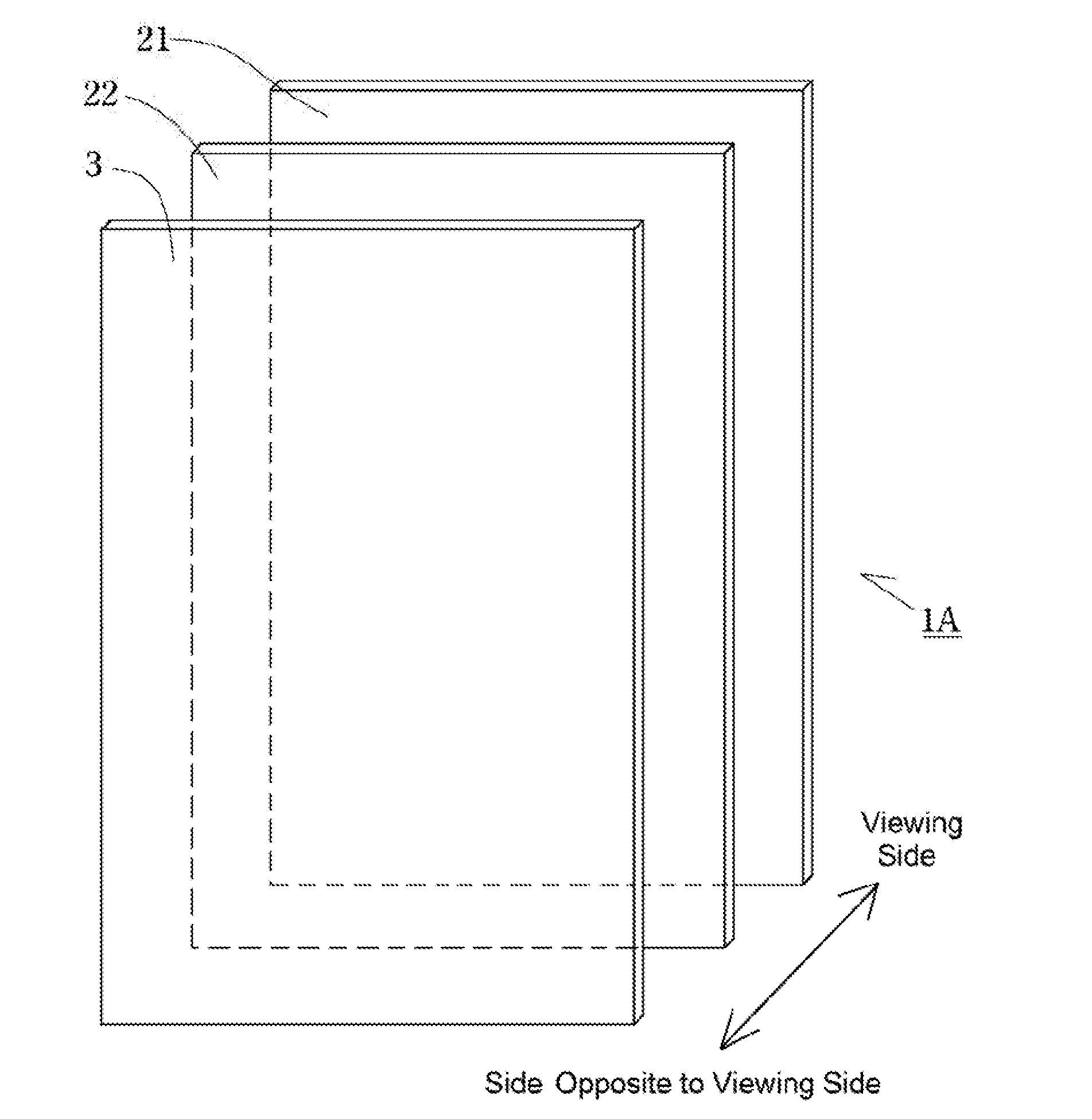
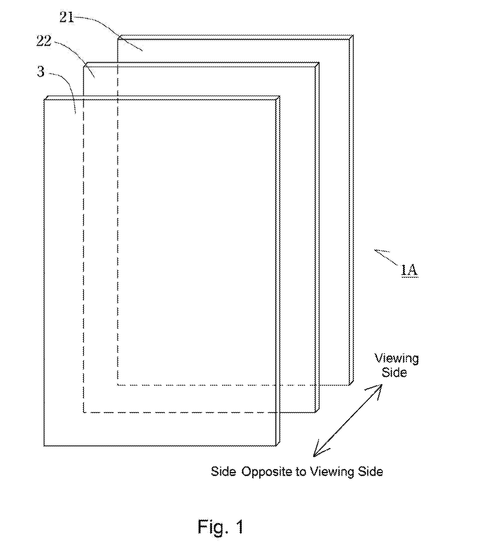
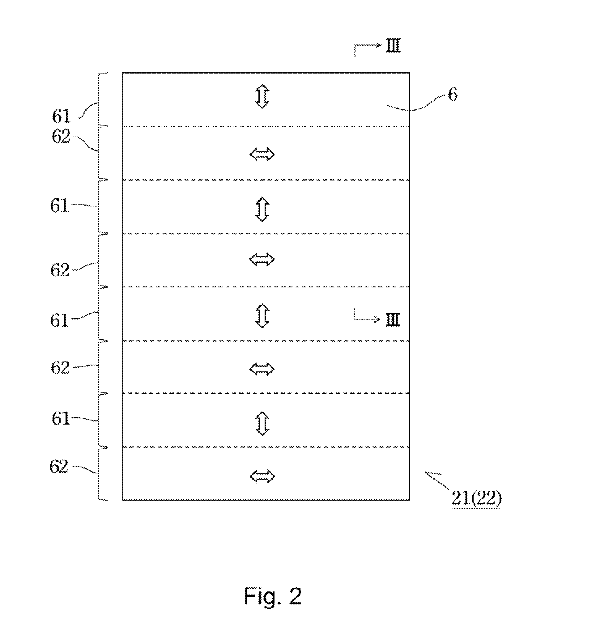
A light control device of the present invention includes a first patterning polarizing plate 21 containing a plurality of polarization regions having different absorption axis directions, a second patterning polarizing plate 22 containing the same polarization regions as those of the first patterning polarizing plate 21, and a retardation plate 3, wherein at least any one of the first and the second patterning polarizing plates 21, 22 is disposed slidably in a plane direction. Such a light control device hardly causes color irregularities and hardly causes a pattern.

Description

TECHNICAL FIELD[0001]The present invention relates to a light control device capable of adjusting a transmission quantity of light.BACKGROUND ART[0002]Hitherto, there has been known a patterning polarizing plate containing a plurality of polarization regions having different absorption axis directions, and there has been known that a light control device can be configured with use of two of the polarizing plate (e.g., Patent Document 1).[0003]Specifically, the patterning polarizing plate contains a first polarization region having an absorption axis in a certain direction, and a second polarization region having an absorption axis in a direction orthogonal to the absorption axis direction of the first polarization region, and the first polarization region and the second polarization region are alternately arranged in a plane. Further, by disposing two of the above polarizing plates in parallel so as to face each other, a light control device can be formed.[0004]In the light control ...

Claims


Application Information

Patent Timeline
Patent Type & Authority Applications(United States)
IPC IPC(8): G02B27/28E06B9/24G02B5/30
CPCG02B27/281G02B5/3083E06B2009/2405E06B9/24G02B5/3016
Inventor ASANOI, YOSHIAKIMATSUDA, SHOICHITAKEMOTO, HIROYUKIKAMEYAMA, TADAYUKI
Owner NITTO DENKO CORP
Learn More