Image reading apparatus and image reading method

a technology of image reading and reading method, which is applied in the field of image reading apparatus, can solve the problems of insufficient light to cope with the reading of such a security document, the amount of light used for double-sided original reading, and the effect of correction techniqu

Active Publication Date: 2008-03-20
CANON KK
View PDF2 Cites 30 Cited by
  • Summary
  • Abstract
  • Description
  • Claims
  • Application Information

AI Technical Summary

Benefits of technology

[0013]The present invention provides an image reading apparatus and an image reading method which are capable of preventing images read from a double-sided original from suffering an in-surface color irregularity (density irregularity) on each of images read from the respective opposite sides of a double-sided original and / or color differences (density differences) between the read front-side and reverse-side images.

Problems solved by technology

However, in the image reading apparatus configured to read both sides of an original during one-time conveyance, differences between image reading positions of the respective image readers can cause variation in the amount of light used for double-sided original reading.
To read such a paper document formed by the additional use of a security technique as described above, strict in-surface uniformity (uniformity over one surface of an original) of the read data is required, and hence the correction technique mentioned above is not enough to cope with the reading of such a security document.
Further, the correction technique also suffers from the problem of being incapable of coping with a case in which the front side of an original and the reverse side of the same are largely different in reading characteristics.
Furthermore, an image reading apparatus employing the correction technique is required to have not only a system for shading correction, but also a circuit for correcting shading correction data, which inevitably makes the apparatus large-sized and complicated in configuration, thereby causing an increase in manufacturing costs.
Particularly in the case of reading both sides of an original by the moving original reading method, read values obtained by reading the front side of an original differ from read values obtained by reading the reverse side of the same, which brings about the problems of a density difference occurring in monochrome original copying and a color difference occurring in color original copying.

Method used


Image

  • Image reading apparatus and image reading method
  • Image reading apparatus and image reading method
  • Image reading apparatus and image reading method

Examples


first embodiment

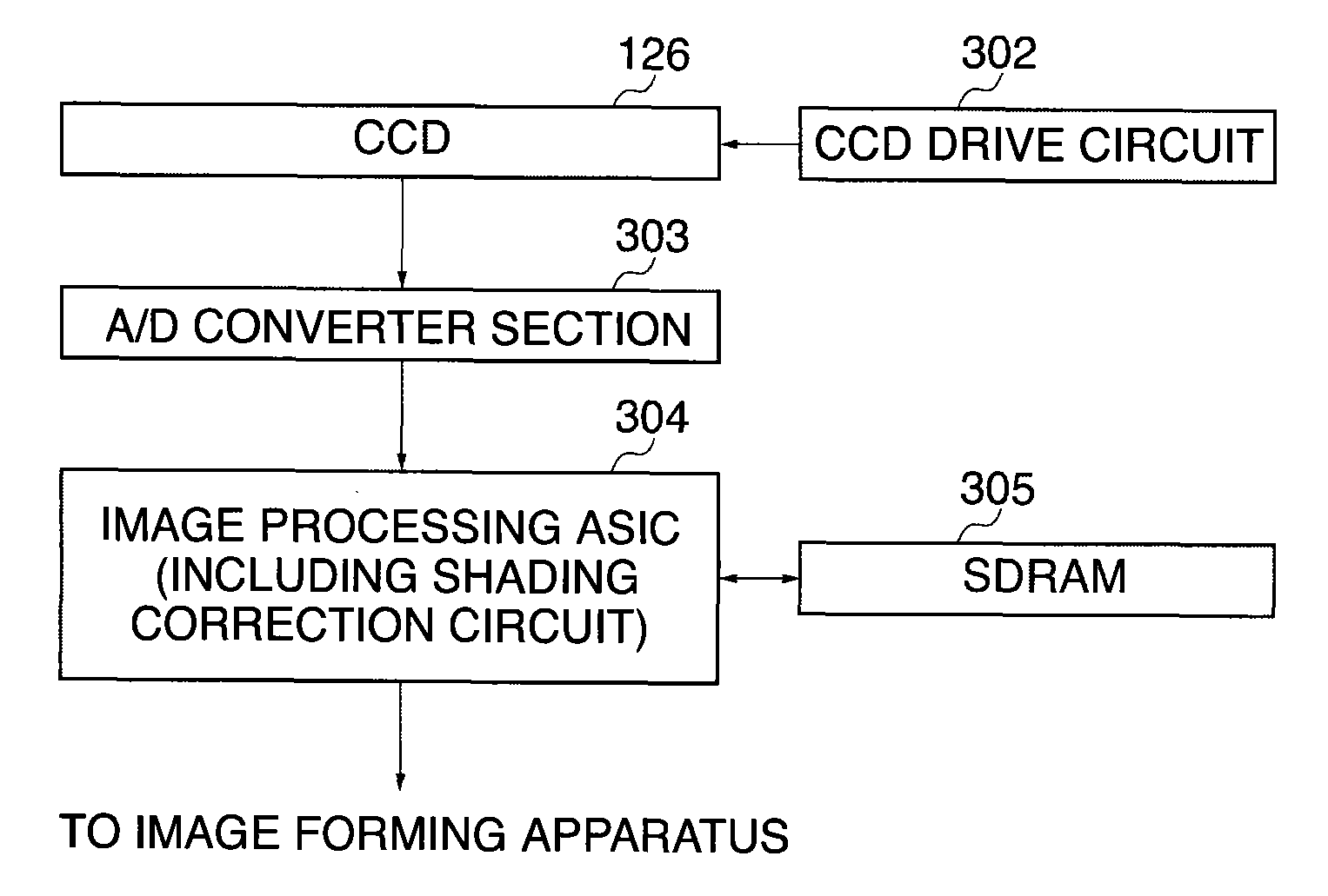
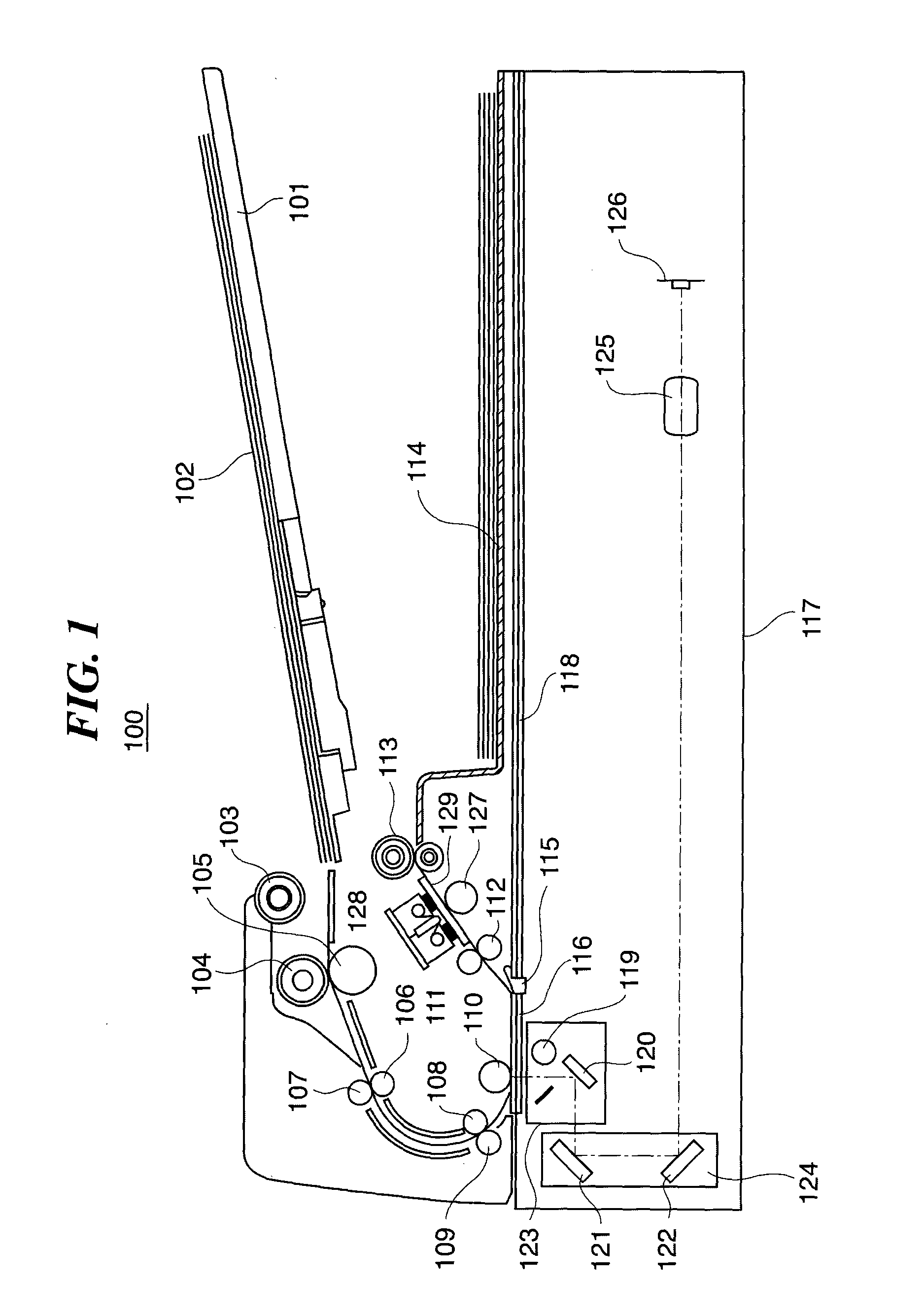
[0051]FIG. 1 is a view of an image reading apparatus according to the present invention.

[0052]As shown in FIG. 1, the image reading apparatus is comprised of an automatic document feeder 100, and an image reading apparatus main unit 117.

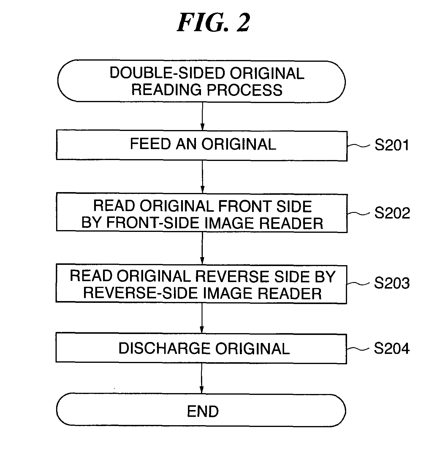
[0053]FIG. 2 is a flowchart of a double-sided original reading process executed by the image reading apparatus shown in FIG. 1.

[0054]In the following, the arrangement of the image reading apparatus will be described together with operations shown in FIG. 2.

[0055]First, originals 102 are stacked on an original tray 101 of the automatic document feeder 100. A sheet feed roller 103 is disposed above the front end of the original tray 101. The sheet feed roller 103 is connected to the same driving power source as a separating and conveying roller 104 is, and rotates along with rotation of the driving power source to feed each original (step S201).

[0056]The sheet feed roller 103 is normally in to a retracted home position above the front end of the origin...

third embodiment

[0117]Next, a third embodiment will be described with reference to FIGS. 15 to 17. In the present embodiment, a description will be given of matching of in-surface reading characteristics and front-side and reverse-side reading characteristics in a case where two patches are selected from each of the low-density portion and the high-density portion, i.e. in a case where four patches are selected. More specifically, the description will be given of a case where a patch with a density of 0.15 and a patch with a density of 0.45 are selected from the low-density portion, and a patch with a density of 1.00 and a patch with a density of 1.79 from the high-density portion, for matching over in-surface reading characteristics and between the front-side reading characteristics and the reverse-side reading characteristics.

[0118]FIG. 15 is a conceptual view of four-point correction of the density linearity characteristic.

[0119]As is understood from FIG. 15, in the case of correcting the densit...

fourth embodiment

[0125]Next, a fourth embodiment will be described with reference to FIGS. 18 and 19.

[0126]In the above-described first to third embodiments, the method of matching the reading characteristics in the main scanning direction or between the front-side and reverse-side reading characteristics was described in detail.

[0127]Actually, however, even patches with the same density can cause large differences in the reading characteristics depending on the conditions of an original surface, i.e. depending on whether the original surface is glossy and “slippery” or non-glossy and “rough”.

[0128]FIGS. 18A and 18B are diagrams showing a density linearity characteristic in a case where an original has gloss and a density linearity characteristic in a case where an original has no gloss.

[0129]FIG. 18A shows the density linearity characteristics in the whole density range, and FIG. 18B shows the high density range thereof on an enlarged scale. As is understood from FIGS. 18A and 18B, the density line...


PUM

PropertyMeasurementUnit
densityaaaaaaaaaa
reflectanceaaaaaaaaaa
luminanceaaaaaaaaaa

Abstract

An image reading apparatus which is capable of preventing images read from a double-sided original from suffering an in-surface color irregularity on each of images read from the respective opposite sides of a double-sided original and a color difference between the front and reverse. A CCD line sensor reads a front-side original image. An image processing ASIC calculates shading correction data for performing shading correction on original image data read from the original image by the CCD line sensor, based on read luminance values obtained by the CCD line sensor by reading a plurality of halftone gradation patches thereon on a correction chart. The shading correction data calculated by the image processing ASIC is corrected based on read luminance values associated, respectively, with at least two of the gradation patches.

Description

BACKGROUND OF THE INVENTION[0001]1. Field of the Invention[0002]The present invention relates to an image reading apparatus for a digital copying machine, a facsimile machine, a scanner, or the like, and an image reading method executed by the image reading apparatus, and more particularly to an image reading apparatus configured to be capable of performing simultaneous double-sided reading for simultaneously reading both sides of an original during one-time conveyance of the original, and an image reading method executed by the image reading apparatus.[0003]2. Description of the Related Art[0004]Recently, a series of system developments concerning filing applications for various official certificates and notifications to public offices have been being vigorously promoted based on the electronic government concept. Such movement can also be widely seen among private companies, and with a rise in interest in security of personal information and an increase in demand for security of s...

Claims


Application Information

Patent Timeline
Patent Type & Authority Applications(United States)
IPC IPC(8): G03F3/00
CPCH04N1/00002H04N1/00013H04N1/00031H04N1/00045H04N1/00053H04N2201/0081H04N1/00087H04N1/12H04N1/193H04N1/203H04N1/00063
Inventor MORIKAWA, DAISUKE
Owner CANON KK
Why Eureka
Try Eureka