Optical beam scanning device and image forming apparatus
Inactive Publication Date: 2004-11-04
KK TOSHIBA +1
View PDF0 Cites 10 Cited by
Summary
Abstract
Description
Claims
Application Information
AI Technical Summary
This helps you quickly interpret patents by identifying the three key elements:
Problems solved by technology
Method used
Benefits of technology
Benefits of technology
[0013] Moreover, another object of the present invention is to restrain the light amount irregularity of each scanning line in the image plane and provide the light amount ratio of each scanning line equally regardless of the position in the main scanning direction in an image forming apparatus utilizing light beams from a plurality of light sources.
Problems solved by technology
Therefore, it is difficult to constantly maintain the light amount.
In the case the polarization direction is changed, the light focusing position, or the like is changed as well so that the image forming characteristic is deteriorated as a result, and thus a problem is involved in that the beam cannot be focused, flare is increased, or the like.
However, an adjusting mechanism is needed so as to give rise to cost increase, such as the need of the steps for adjustment.
However, as a conventional method, a method of utilizing semiconductor lasers of the same characteristic, or the like has been provided, and the apparatus range with the method usable has been limited.
Method used
Image
Click on the blue label to locate the original text in one second.
Reading with bidirectional positioning of images and text.
Examples
first embodiment
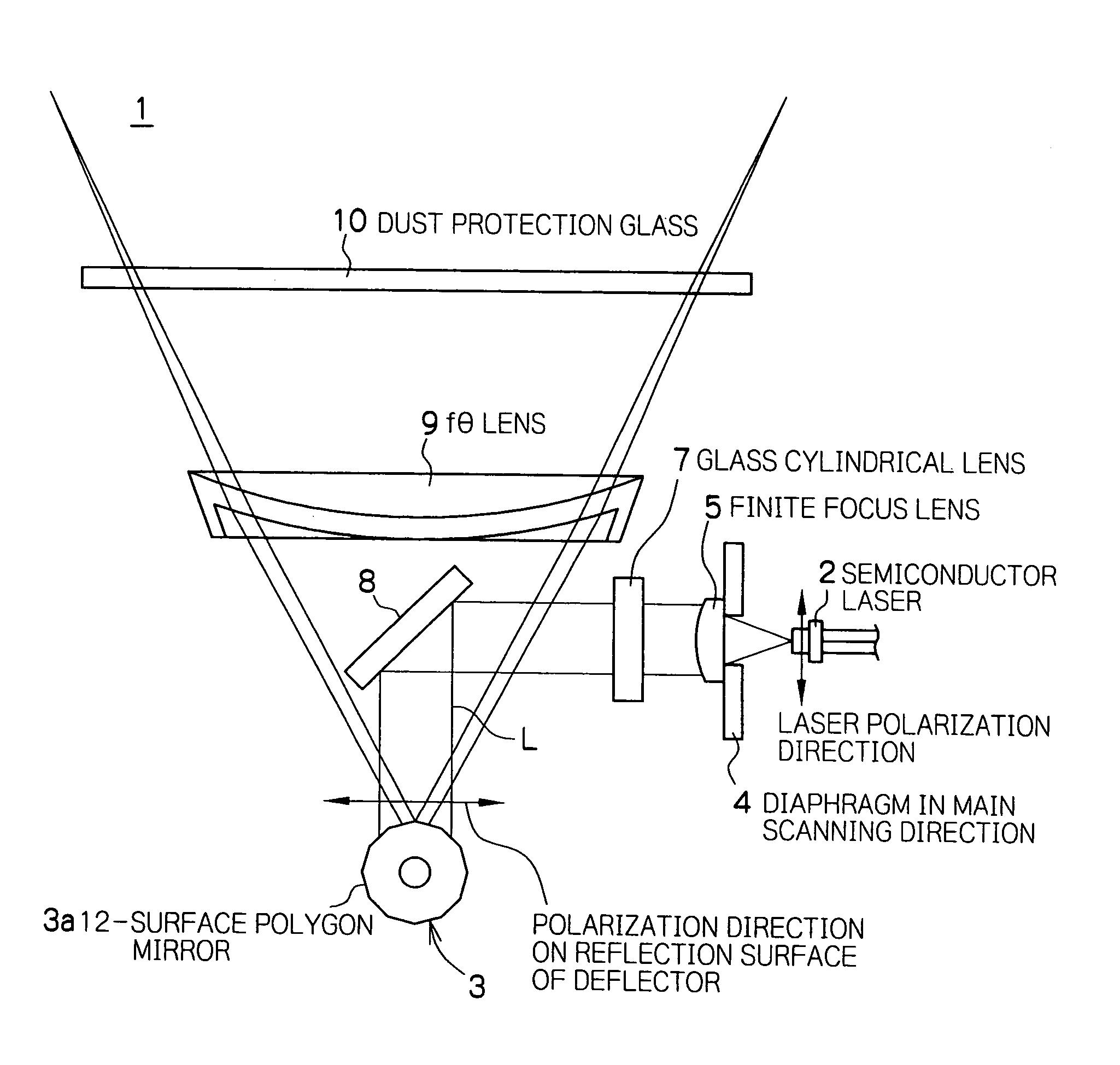
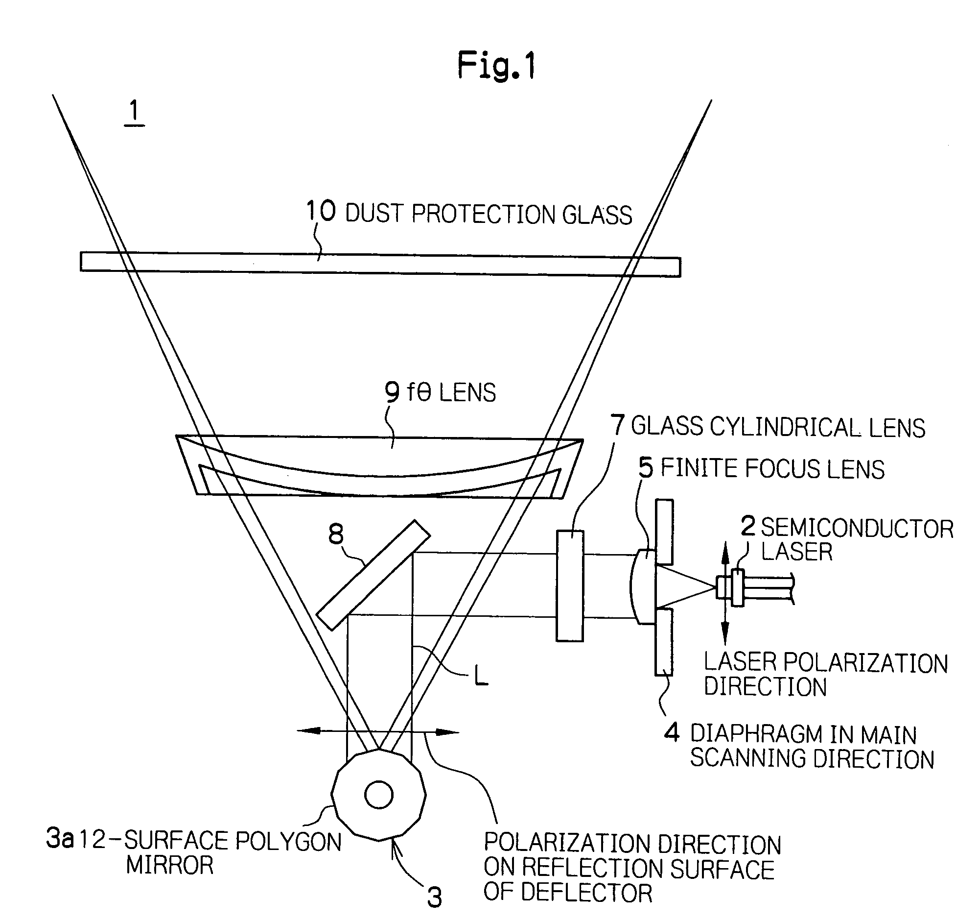
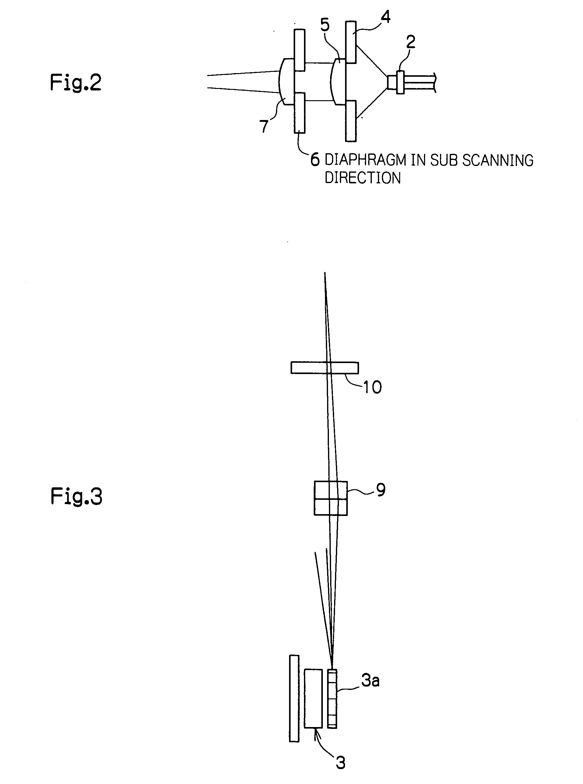
[0075] FIG. 1 is a schematic plane view showing an optical beam scanning device 1 of the first embodiment used for an image forming apparatus along the main scanning direction. FIG. 2 is a schematic cross-sectional view showing the principal elements of a pre-deflection optical system (light source side) of the optical beam scanning device 1 along the sub scanning direction. FIG. 3 is a schematic cross-sectional view showing the principal elements of a post-deflection optical system (image plane side) of the optical beam scanning device 1 along the sub scanning direction.
[0076] In FIGS. 1 to 3, the optical beam scanning device 1 of the first embodiment comprises an optical deflecting device 3 for deflecting a laser beam output from a semiconductor laser 2 as the light source to a predetermined position of an image plane (for example, a photosensitive drum, not shown) disposed at a predetermined position by a predetermined linear velocity. In the description below, the direction of d...
second embodiment
[0145] Next, a second embodiment of the present invention will be explained. The second embodiment is characterized in the optical beam scanning device.
[0146] Compared with the first embodiment, the optical beam scanning device of the second embodiment has a different semiconductor laser 2 configuration, and the configuration other than the semiconductor laser 2 is same as that of the first embodiment (see FIGS. 24 to 26). That is, the second embodiment is characterized in the configuration of the semiconductor laser 2 for having the P polarized light beam incident on the deflector (polygon mirror) 3.
[0147] According to the semiconductor laser having two laser arrays, in the case the two laser arrays are disposed side by side in the sub scanning direction as shown in FIG. 27, the polarization direction on the deflector reflection surface becomes the S polarized light beam. Therefore, for example, as shown in FIG. 28, by having the array interval sufficiently large with respect to th...
third embodiment
[0161] Next, a third embodiment of the present invention will be explained. The third embodiment is characterized in the image forming apparatus.
[0162] FIG. 31 is a schematic vertical cross-sectional view showing the configuration of the color image forming apparatus according to the third embodiment.
[0163] A color image forming apparatus 20 comprises optical beam scanning devices 21Y, 21M, 21C, 21B for yellow, magenta, cyan and black, and an image forming section 30. The optical beam scanning devices for yellow, magenta, cyan and black 21Y, 21M, 21C, 21B each directs the laser beam LY, LM, LC, LB to a photosensitive drums 22Y, 22M, 22C, 22B of the corresponding image forming section 30 so as to write a latent image of yellow, magenta, cyan and black components and form the toner images by the developers 23Y, 23M, 23C, 23B for developing the yellow, magenta, cyan and black toners. Onto a paper fed out from a paper tray 24 and being conveyed by a conveyance belt 25, the toner images ...
PUM
Abstract
The present invention provides an optical beam scanning device and an image forming apparatus capable of restraining the light amount irregularity in the main scanning direction in the image plane. An optical beam scanning device of the present invention is for having a light beam with the width in the main scanning direction wider than the width in the main scanning direction of the reflection surface of a deflector incident on the deflector, reflecting and polarizing a part thereof by the reflection surface of the deflector, and focusing the polarized light beam on a surface to be scanned by optical means including a transmission type optical member. Then, the polarization direction of the light beam incident on the deflector is substantially in the main scanning direction. According to an image forming apparatus comprising a plurality of light sources for forming a plurality of scanning lines with the light beams from a plurality of the light sources, the polarization direction of the light beams from the light sources at the time of being incident on the corresponding deflector is provided substantially in the main scanning direction.
Description
[0001] 1. Field of the Invention[0002] The present invention relates to an image forming apparatus such as a laser printer, and a digital copyingmachine, and an optical beam scanning device to be used for an image forming apparatus.[0003] 2. Description of the Related Art[0004] Conventionally, the optical beam scanning device has been applied widely as for example an optical system for supplying a laser beam to an image forming section for forming a latent image on a photosensitive member based on image data in an image forming apparatus such as a laser printer and a digital copyingmachine.[0005] Such an optical beam scanning device comprises a semiconductor laser element (laser diode) as a light source, a (light sources side) pre-deflection optical system for narrowing the cross-sectional shape of a laser beam output from the laser diode or the like to a predetermined size, a scanning optical system for deflecting the narrowed laser beam by a rotatable polygon mirror in the photo...
Claims
Application Information
Patent Timeline
Application Date:The date an application was filed.
Publication Date:The date a patent or application was officially published.
First Publication Date:The earliest publication date of a patent with the same application number.
Issue Date:Publication date of the patent grant document.
PCT Entry Date:The Entry date of PCT National Phase.
Estimated Expiry Date:The statutory expiry date of a patent right according to the Patent Law, and it is the longest term of protection that the patent right can achieve without the termination of the patent right due to other reasons(Term extension factor has been taken into account ).
Invalid Date:Actual expiry date is based on effective date or publication date of legal transaction data of invalid patent.

