Stapler

Inactive Publication Date: 2008-12-11
SEBEK
View PDF24 Cites 10 Cited by
  • Summary
  • Abstract
  • Description
  • Claims
  • Application Information

AI Technical Summary

Benefits of technology

[0044]In accordance with the first aspect of the present invention, the stapler includes vertical movement means for causing the operating handle to vertically descend together with the staple mounting magazine by pressing the operating handle while keeping the operating handle at the predetermined angle and post-vertical movement rotating means that can start rotation of the operating handle after the staple mounting magazine vertically descends to come into contact with a paper bundle placed on the horizontal base. Thus, a staple, after being guided to a vicinity of a surface of the paper bundle while mounted in the staple mounting magazine, is pushed into the surface of the paper bundle by rotating the operating handle. Therefore, the paper bundle is not stapled obliquely and irregularities of the stapled paper bundle can be prevented.
[0045]In accordance with the second aspect of the present invention, the stapler includes magazine vertical position fixing means for fixing the vertical position of the staple mounting magazine by starting the rotation of the operating handle. Thus, after being felt that the staple mounting magazine has been brought into contact with the surface of the paper bundle, the staple can be pushed into the paper bundle by rotating the operating handle. Therefore, a timing when a staple should be pushed into the paper bundle becomes easier to understand.
[0046]In accordance with the third aspect of the present invention, the vertical movement means is a pantograph causing the staple mounting magazine to descend and ascend on the horizontal base. Thus, the staple mounting magazine is caused to descend and ascend while keeping a parallel state with the horizontal base by operating a pantograph mechanism. Therefore, a structure of descent and ascent of the staple mounting magazine can be simplified.
[0047]In accordance with the fourth aspect of the present

Problems solved by technology

However, since the operating handle rotates around a specific one point, the inclination of a staple pushed out of the staple moun

Method used


Image

  • Stapler
  • Stapler
  • Stapler

Examples


first embodiment

of the Invention

[0085]A first embodiment of the present invention will be described below.

[0086]FIGS. 1 to 7 show the first embodiment of the present invention.

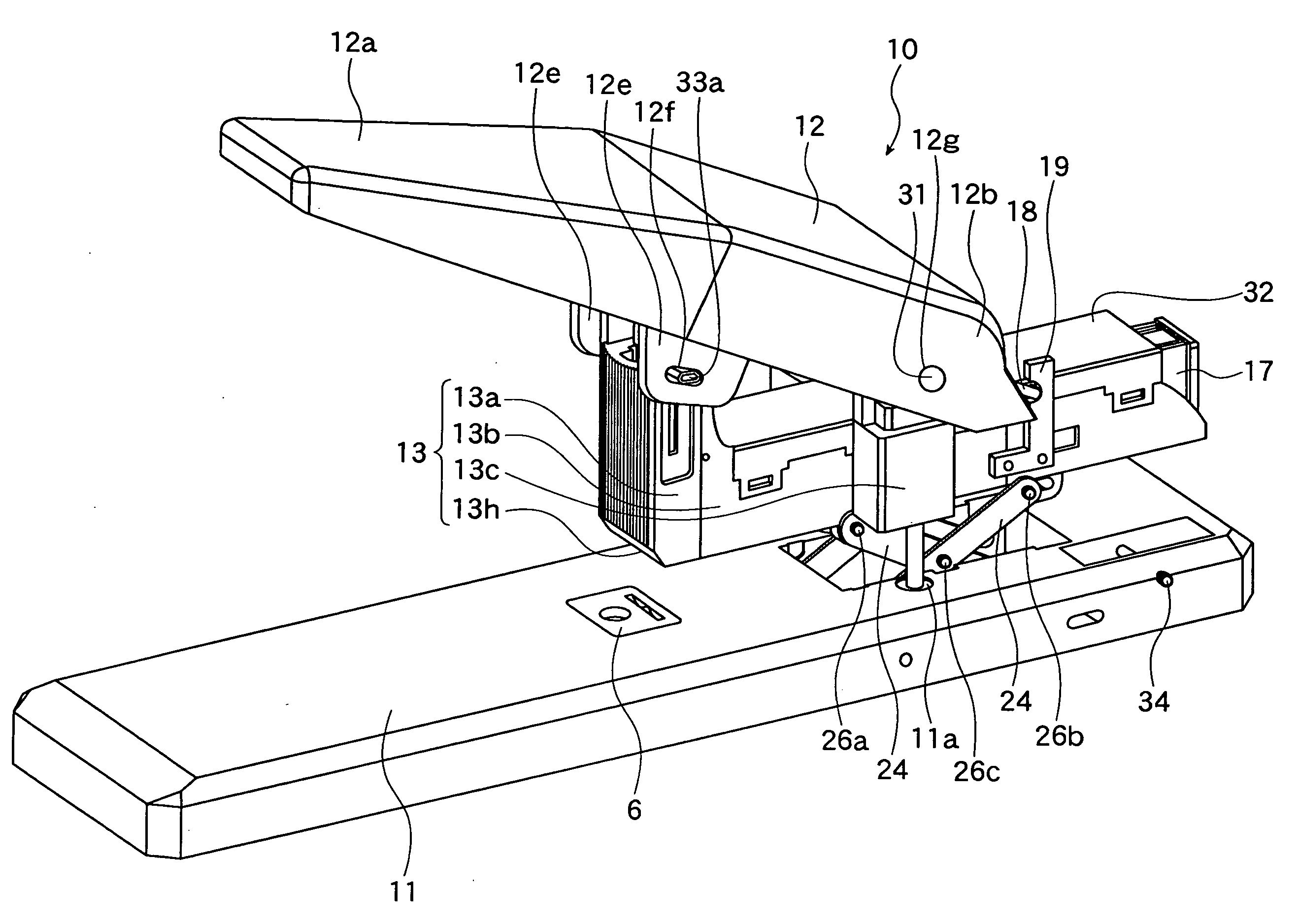
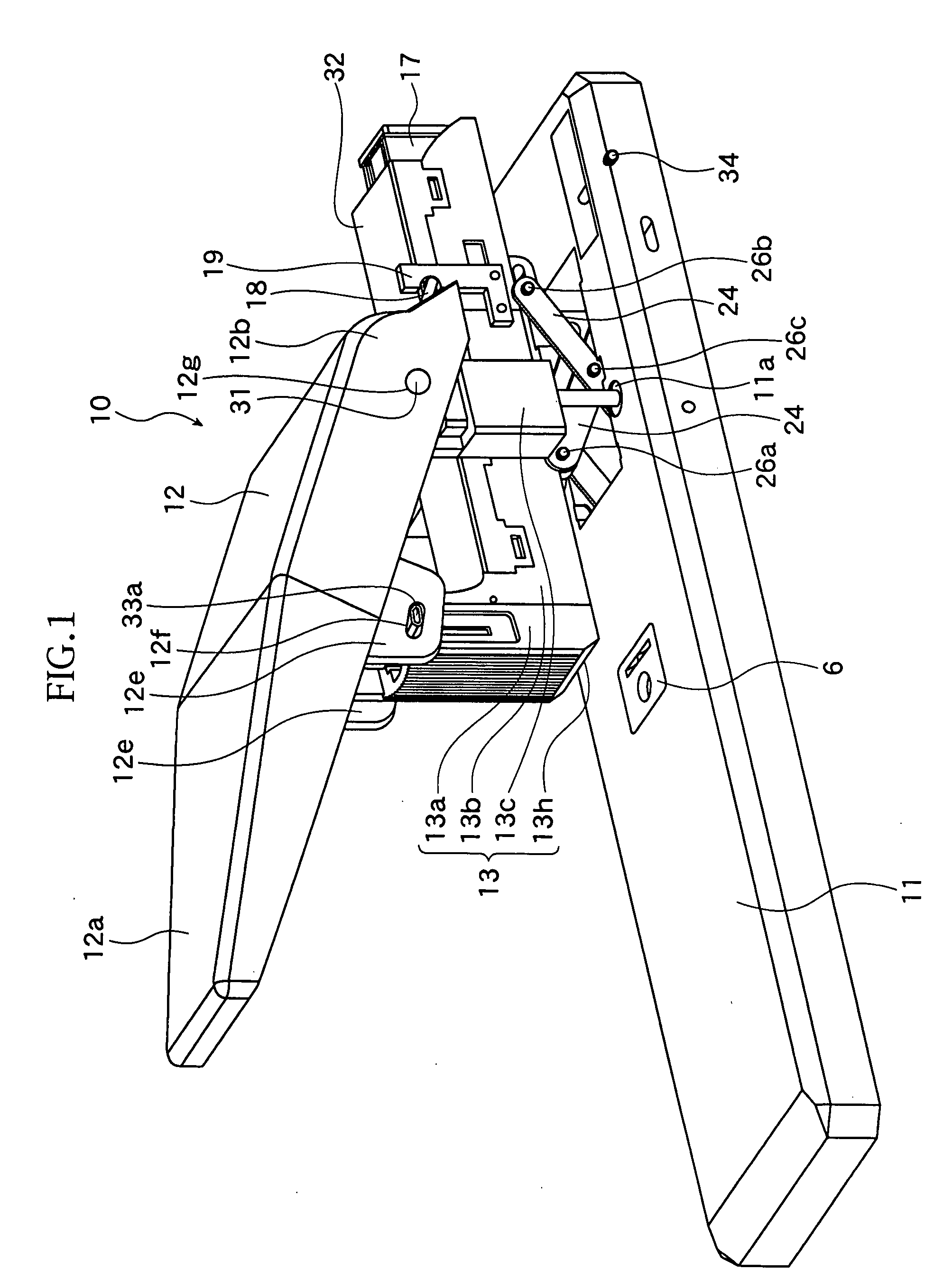
[0087]As shown in FIG. 1, a stapler 10 includes a horizontal base 11 having an anvil 6 for bending a staple from lower ends, an operating handle 12 that has a pinching portion 12e pinching a supporter 33a of a fitting member 33a supporting a staple pushing blade 15 (See FIGS. 6 and 7) and can be pressed by hand, and a staple mounting magazine 13 in which staples are housed.

[0088]The operating handle 12 is provided with a handle spring 18 (See FIG. 6), which is a rotation direction elastic member, and the staple mounting magazine 13 is provided with a spring fastener 19 to which the handle spring 18 is engaged so that the handle spring 18 slides upward along a back side of the operating handle 12, and the operating handle 12 can rotate around a rotating shaft 31.

[0089]As shown in FIG. 1, the staple mounting magazine 13 is a me...

second embodiment

of the Invention

[0128]A second embodiment of the present invention is different from the first embodiment of the present invention in that handle springs 41 and 42, which are rotation-direction elastic members for connecting the horizontal base 11 and operating handle 12, are used without using the handle spring 18.

[0129]In FIG. 8, the same reference numerals are used for the same members as those in the first embodiment and a stapler in FIG. 8 shall be a stapler 40 in the second embodiment of the present invention.

[0130]As shown in FIG. 8, the handle springs 41 and 42 have handle-side linear portions 41a and 42a and base-side linear portions 41b and 42b, and twist portions 41c and 42c between the handle-side linear portions 41a and 42a and the base-side linear portions 41b and 42b. The handle-side linear portions 41a and 42a are fixed to the back side of the operating handle 12 and the base-side linear portions 41b and 42b are fixed onto the horizontal base 12. The operating handle...

third embodiment

of the Invention

[0132]A third embodiment of the present invention will be described below. FIGS. 9 to 12 show the third embodiment of the present invention.

[0133]As shown in FIGS. 9 and 10, a stapler 50 includes a horizontal base 51, an operating handle 52 arranged at a predetermined angle with respect to the horizontal base 51, a staple mounting magazine 53 attached to the operating handle 52 to mount a staple connecting assembly cassette 57 in which a staple connecting assembly connecting many staples is housed, and a staple pushing blade (not shown) brought down on a staple housed in the staple mounting magazine 53. The operating handle 52 is freely rotatably connected to a case 59 provided on the horizontal base 51 and can rotate around a lever rotating shaft 58, which is a connecting position. Then, the staple mounting magazine 53 is pinched and housed in the case 59. A paper end guide 61 formed like in an L shape as a side view is disposed on the horizontal base 51.

[0134]As sh...


PUM


Abstract

A stapler that can push staples into a surface of a paper bundle regardless of thickness of the paper bundle is provided.
A stapler including vertical movement means (24) for causing an operating handle (12) to vertically descend together with a staple mounting magazine (13) by pressing the operating handle (12) while keeping the operating handle at a predetermined angle, post-vertical movement rotating means (18, 27) for causing the operating handle (12) to rotate after the staple mounting magazine (13) vertically descends to come into contact with the paper bundle placed on a horizontal base, and vertical position fixing means (21, 22, 28) for fixing a vertical position of the staple mounting magazine (13) by starting the rotation of the operating handle (12) has been constructed.

Description

TECHNICAL FIELD[0001]The present invention relates to a stapler including a horizontal base, an operating handle, a staple pushing blade, and a staple mounting magazine to mount a staple connecting assembly cassette housing a staple connecting assembly that connects many staples.BACKGROUND ART[0002]In a conventional stapler, a staple mounting magazine housing a staple connecting assembly is fixed to a horizontal base by a main shaft and an operating handle that is rotatable around the main shaft is provided. Then, if the operating handle is rotated around the main shaft, a staple mounted in the staple mounting magazine is brought into contact with a surface of a paper bundle placed on the horizontal base before the paper is stapled.[0003]However, since the operating handle rotates around a specific one point, the inclination of a staple pushed out of the staple mounting magazine is not constant depending on thickness of the paper bundle, posing a possibility of irregularly stapled p...

Claims


Application Information

Patent Timeline
IPC IPC(8): B25C5/06
CPCB25C5/0242B25C5/11
Inventor KUMAYAMA, MICHIHITO
Owner SEBEK
Why Eureka
Try Eureka